2026 Conformal Cooling Design Playbook: Reduce Warpage and Cycle Time in High-Precision Molds
You have likely seen it on your own production floor: a precision connector housing, a thin-wall medical device component, or an optical lens that comes out of the mold within spec on one shift and drifts out of tolerance on the next. The root cause is rarely the material or the press. It is almost
Why High-Precision Molds Are Hitting a Wall with Warpage and Cycle Time
You have likely seen it on your own production floor: a precision connector housing, a thin-wall medical device component, or an optical lens that comes out of the mold within spec on one shift and drifts out of tolerance on the next. The root cause is rarely the material or the press. It is almost always non-uniform cooling.
Conventional cooling circuits—straight-drilled lines that intersect at right angles—leave dead zones where heat extraction lags. The result is differential shrinkage across the part geometry. One region solidifies and contracts while an adjacent region is still cooling, building residual stress that releases as warpage after ejection. For high-precision molds holding tolerances under ±0.05 mm, this is a silent yield killer.
The data backs this up. In a documented case study from voestalpine HPM, switching to conformal cooling reduced warpage by up to 61% on a demanding production part, bringing the scrap rate down from double digits to just 1%. That is not a marginal improvement—it is the difference between a profitable program and a net loss.
Cycle time tells a parallel story. Cooling typically consumes 60–70% of the total molding cycle. When you rely on straight-drilled channels that cannot follow complex contours, you are forced to extend cooling time to let the thickest sections catch up. MouldNova's analysis shows that conformal cooling simulations consistently deliver 30–50% cooling time reduction. On a 50-second cycle, a 40% reduction recovers 20 seconds per shot. Across 600,000 shots per year, that is 3,333 press hours recovered—capacity you can redeploy without buying another machine.
Key Takeaway: The wall that high-precision molds are hitting is thermal. Warpage and excessive cycle time are symptoms of the same underlying problem: heat removal that does not match part geometry. Conformal cooling addresses the root cause, not the symptom.
How Conformal Cooling Channels Actually Work — and Why Uniform Cooling Changes Everything
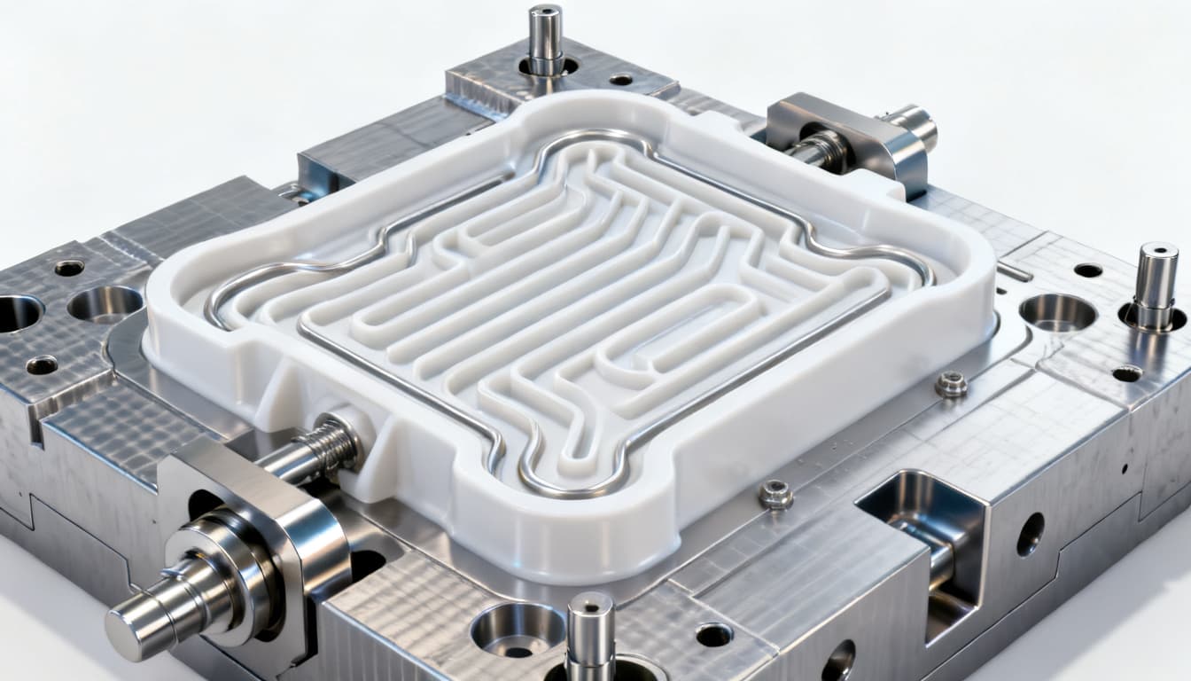
Conformal cooling channels are not simply "curved cooling lines." They are a fundamentally different approach to heat management in injection molds. Instead of drilling straight lines that intersect the part cavity at varying distances, conformal channels are designed to follow the contour of the part surface at a consistent offset—typically 1.5 to 2.5 times the channel diameter from the cavity wall.
This consistent proximity means every square millimeter of the part surface sees roughly the same rate of heat extraction. The physics is straightforward: heat transfer from the polymer melt to the coolant is governed by the thermal gradient and the distance the heat must travel through the tool steel. When that distance varies from 3 mm to 15 mm across a single part—as it often does with straight-drilled circuits—you get hot spots and cold spots. Conformal channels collapse that range to a narrow band, typically within ±1 mm of the target offset.
Polyshot describes the outcome clearly: uniform cooling minimizes warpage, residual stresses, and the cascade of defects associated with uneven thermal conditions. Xometry adds that custom-designed channels reduce sink marks, weld lines, and differential shrinkage, directly improving part consistency. And as PTI.Tech notes, different areas of a conventionally cooled part cool at different rates, leading to differential shrinkage that manifests as warpage once the part is ejected. Conformal cooling solves this by ensuring uniform cooling throughout the part geometry.
The table below quantifies the differences between conventional and conformal cooling across the metrics that matter most to engineers and buyers.
| Parameter | Conventional Straight-Drilled Cooling | Conformal Cooling (DMLS/SLM Inserts) | Impact on Part Quality |
|---|---|---|---|
| Channel-to-cavity distance | Varies widely (3–20+ mm depending on geometry) | Consistent offset (1.5–2.5× channel diameter) | Eliminates hot spots; uniform shrinkage |
| Cooling time as % of cycle | 60–70% (extended for thick sections) | 30–50% reduction in cooling time | 20–30% overall cycle time savings |
| Temperature variation across part | 15–30°C delta common on complex parts | Typically <5°C delta achievable | Dramatically reduced warpage |
| Warpage reduction potential | Baseline | 7.5–61% reduction documented | Parts within tolerance; scrap <3% |
| Residual stress | High in thick-to-thin transitions | Low and uniform across part | Improved dimensional stability post-ejection |
| Surface finish on Class-A surfaces | Prone to sink marks and flow lines | Uniform surface quality; fewer defects | Reduced secondary operations |
| Channel geometry freedom | Straight lines only; right-angle intersections | Free-form curves; helical, spiral, branching | Cooling where it is actually needed |
| Pressure drop across circuit | Predictable; standard calculations apply | Requires simulation; can be optimized | Balanced flow with proper design |
| Compatible mold types | All standard mold bases | Insert-based; hybrid molds; full 3D-printed cores | Retrofit possible on existing tools |
What this table does not capture is the compounding effect. When cooling is uniform, you can often reduce pack and hold times because the part solidifies evenly. Ejection temperatures are consistent, so you can automate demolding with greater reliability. The benefits cascade through the entire molding cycle.
Note: Uniform cooling does not mean "coldest possible." For semi-crystalline resins like PEEK or PPS, maintaining an elevated, uniform mold temperature is often the goal—and conformal channels can deliver that uniformity at 180°C or higher just as effectively as they can at 30°C.
Conformal vs. Conventional Cooling: When the Investment Pays Off
Not every mold needs conformal cooling. If you are running a simple, flat part with generous tolerances and a 30-second cycle, straight-drilled channels will serve you perfectly well. The decision to invest in conformal cooling inserts—typically manufactured via DMLS (Direct Metal Laser Sintering) or SLM (Selective Laser Melting)—should be driven by specific thermal and economic thresholds.
MouldNova's engineering guides highlight several scenarios where conformal cooling delivers outsized returns: Class-A surfaces where sink marks are unacceptable, optical parts requiring birefringence-free molding, thin-wall packaging where every fraction of a second in cycle time matters, and high-temperature engineering resins where uniform mold temperature is critical for crystallinity and dimensional stability. The common thread is that the cost of non-conformance—scrap, rework, slower cycles, or missed deliveries—exceeds the incremental cost of the conformal insert.
Mantle3D emphasizes another dimension: design flexibility. Conformal cooling expands what is moldable. You can design parts with thick-to-thin transitions, deep ribs, or complex bosses that would warp unacceptably with conventional cooling. This frees product designers from having to compromise part function for manufacturability.
The comparison below frames the decision across the factors that procurement teams and engineering managers actually weigh.
| Comparison Metric | Conventional Straight-Drilled Cooling | Conformal Cooling (AM Inserts) | Selection Criteria & Break-Even Guidance |
|---|---|---|---|
| Tooling cost (insert only) | Included in standard mold build; negligible adder | $3,000–$15,000+ per insert depending on size and complexity | Justified when scrap reduction alone recovers cost within 50k–100k shots |
| Lead time impact | No impact; standard machining timeline | Adds 2–4 weeks for AM build + post-processing | Acceptable when cycle time savings recover the delay within first production month |
| Cycle time reduction | Baseline | 30–50% cooling time reduction typical | High-value: parts with cooling-limited cycles >30 seconds |
| Warpage control | Limited to what part design and material allow | 7.5–61% warpage reduction documented | Critical when tolerances are <±0.05 mm or scrap rate exceeds 5% |
| Part geometry complexity | Simple to moderate; deep contours create dead zones | Handles complex 3D contours, deep ribs, and variable wall thickness | Threshold: when any cavity surface is >8 mm from nearest cooling line |
| Maintenance and cleaning | Straightforward; standard cleaning procedures | Requires attention to channel surface finish; may need more frequent flushing | Factor in preventive maintenance schedule; specify polished channel walls |
| Retrofit feasibility | N/A (existing tool) | High; inserts can replace existing cores/cavities in many mold bases | Evaluate when existing mold runs at high utilization but yields are declining |
The break-even math is compelling for the right applications. Voestalpine's cost comparison demonstrated that the break-even point for AM inserts was reached quickly when factoring in scrap reduction from 3% to 1%—and that was before accounting for cycle time savings. When you layer in recovered press capacity, the ROI often materializes in months, not years.
Tip: If you are unsure whether your part crosses the threshold, run a conformal cooling simulation on your existing mold design. Compare the predicted temperature distribution, warpage, and cooling time against your current baseline. The simulation cost is trivial compared to the insight it provides—and it gives you hard numbers to build a capex justification.
Designing and Sourcing Conformal Cooling Inserts: Practical Steps for Engineers and Buyers
Designing a conformal cooling insert is not a "hit print and hope" exercise. It requires deliberate engineering decisions about channel geometry, thermal performance, and manufacturability. The following design rules, drawn from field experience and validated by simulation, will help you avoid the most common pitfalls.
Channel Design Rules That Prevent Failure
Channel diameter, spacing, and proximity to the cavity surface form the three-legged stool of conformal cooling design. Get any one wrong, and performance suffers—or worse, the insert fails mechanically.
| Design Parameter | Recommended Range | Rationale & Failure Boundary |
|---|---|---|
| Channel diameter | 3–8 mm typical; 4–6 mm optimal for most applications | Below 3 mm risks clogging and high pressure drop; above 8 mm reduces structural integrity of the insert |
| Channel spacing (center-to-center) | 2–3× channel diameter | Tighter spacing improves uniformity but increases pressure drop and AM build time; wider spacing creates thermal dead zones |
| Distance from cavity surface | 1.5–2.5× channel diameter | Closer than 1.5× risks surface blemishes and structural weakness under injection pressure; farther than 2.5× diminishes cooling effectiveness |
| Channel wall thickness (to nearest surface) | Minimum 1.5 mm for maraging steel; 2.0 mm for H13 | Thinner walls risk cracking under cyclic thermal and mechanical loads; verify with FEA for high-pressure applications |
| Channel cross-section | Circular preferred; elliptical acceptable where space is constrained | Non-circular channels increase pressure drop and are harder to clean; use only when geometry demands it |
| Surface roughness (Ra) inside channels | <6.3 µm Ra target; <3.2 µm for optical or medical | Rougher surfaces increase flow resistance and fouling risk; specify post-processing (abrasive flow machining) for critical applications |
| Gate area cooling | Dedicated channel loop within 5–8 mm of gate | The gate is the hottest zone; without dedicated cooling, it dictates overall cycle time |
| Hot runner integration clearance | Minimum 3 mm between channel and hot runner components | Thermal interference can destabilize hot runner temperature control; simulate the combined thermal field |
| Pressure drop per circuit | <1.5 bar (22 psi) per circuit at design flow rate | Higher pressure drops require larger pumps and increase energy cost; balance circuits for equal flow resistance |
These parameters are starting points, not absolutes. Every conformal cooling design should be validated through transient thermal FEA simulation before any metal is printed. The simulation should model the full molding cycle—fill, pack, cool, and eject—and predict both the steady-state temperature distribution and the transient thermal response during each shot.
Sourcing Conformal Cooling Inserts: What to Ask and What to Avoid
Not all AM insert suppliers are equal. MouldNova's supplier evaluation framework recommends asking these questions before placing an order:
- What material are you printing with? Maraging steel (MS1, 1.2709) is the workhorse for conformal cooling; H13 is preferred for high-temperature applications. Verify the supplier can provide material certs and heat treatment records.
- What is your as-printed surface finish, and what post-processing do you offer? As-printed DMLS surfaces typically have Ra 8–12 µm. For cooling channels, you want abrasive flow machining or chemical polishing to bring this below 6.3 µm.
- Can you provide a conformal cooling simulation report? If the supplier cannot show you the predicted thermal performance before cutting metal, find another supplier. This is non-negotiable.
- What is your scrap rate on conformal inserts? Experienced suppliers should have first-pass yield above 90% on conformal cooling inserts. Lower yields signal process immaturity.
Red flags: Suppliers who quote without seeing the part geometry, who cannot provide thermal simulation, or who promise "any geometry is possible" without discussing design for AM constraints (minimum wall thickness, support structures, powder removal from channels).
ROI calculation: The payback model is straightforward. Take your annual shot volume, multiply by the cycle time savings per shot, and convert to press hours recovered. Add the value of scrap reduction. Compare against the incremental insert cost. MouldNova's payback data shows that for parts running 500,000+ shots per year with cooling-limited cycles, the conformal insert often pays for itself within 3–6 months of production.
Conformal Cooling Design FAQs: What Senior Engineers and Buyers Need to Know
Q: How much cycle time reduction is realistic with conformal cooling?
Most simulation-backed cases show 30–50% cooling time reduction, which directly translates to overall cycle time savings. For a 50-second cycle, a 40% reduction recovers 20 seconds per shot. At 600,000 shots per year, that frees over 3,300 press hours annually—capacity you can use for additional production without capital expenditure. The actual percentage depends on how cooling-limited your current cycle is. If cooling already represents only 40% of your cycle, the overall cycle time reduction will be proportionally smaller. MouldNova's analysis provides detailed breakdowns by part type.
Q: What minimum production volume justifies the cost of conformal cooling inserts?
Break-even typically occurs within the first 50,000–100,000 shots for high-value parts, especially when scrap reduction and faster cycles are both factored in. For a part with a current scrap rate of 5% and a conformal insert cost of $8,000, the scrap savings alone can recover the investment within 80,000 shots if each scrapped part costs $2 in material and machine time. Add cycle time savings, and the payback accelerates further. Detailed ROI models, like those from MouldNova, show payback can be achieved in months, not years, for parts running at meaningful volumes.
Q: Can conformal cooling completely eliminate warpage?
It dramatically reduces warpage—by up to 61% in documented cases from voestalpine—but may not eliminate it entirely. If the dominant warpage driver is material shrinkage anisotropy (common in glass-fiber-reinforced resins), gate location, or part geometry that creates inherent differential shrinkage even under perfectly uniform cooling, some residual warpage will remain. What conformal cooling reliably does is bring parts within tolerance where conventional cooling fails. If your part is at 0.12 mm warpage and the spec is 0.08 mm, conformal cooling will likely close that gap. If the part is at 0.50 mm and the spec is 0.08 mm, conformal cooling alone may not be enough—you may need to revisit gate location, wall thickness, or material selection as well.
Q: How do I verify cooling performance before cutting steel?
Always run a conformal cooling simulation—a mold flow analysis with transient thermal FEA. This should validate channel layout, pressure drop across each circuit, coolant flow rate requirements, and the resulting temperature uniformity across the cavity surface. The simulation should model at least 10–20 consecutive cycles to reach thermal steady state. For critical applications, consider prototyping the insert in a 3D-printed tooling material (such as a high-temperature photopolymer) for short-run validation, though this will not fully replicate the thermal behavior of a metal insert. 3D Systems offers resources and datasheets that can help you specify simulation parameters.
Q: What are typical lead times for conformal cooling inserts?
Additive manufacturing of inserts typically takes 1–3 weeks, depending on insert size, complexity, and the supplier's queue. Post-processing—heat treatment, support removal, machining of mating surfaces, and channel polishing—adds another 1–2 weeks. Total mold build lead time may extend by 2–4 weeks compared to a conventional mold. However, the cycle time savings from conformal cooling often recover this delay within the first month of production. If you are retrofitting an existing mold with a conformal insert, the lead time is typically 3–5 weeks from approved design to finished insert.
Q: Does conformal cooling work with high-temperature resins like PEEK or PPS?
Yes, but the design approach shifts. For high-temperature semi-crystalline resins, the goal is not maximum heat removal but uniform elevated temperature—typically 160–200°C for PEEK and 130–150°C for PPS. Conformal channels can circulate oil or pressurized water at these temperatures while maintaining uniformity within a few degrees across the cavity. Material selection for the insert is critical: H13 tool steel or maraging steel with appropriate heat treatment is standard. The conformal design must account for thermal expansion of both the insert and the mold base at elevated temperatures. When designed correctly, conformal cooling at high temperatures improves crystallinity uniformity, reduces warpage, and prevents the premature freezing that causes flow lines and poor surface finish in high-temp resins. Mantle3D notes that conformal cooling expands the design envelope for parts with thick and thin sections that would otherwise be impractical to mold in engineering resins.
Putting the Playbook into Practice
The 2026 conformal cooling playbook is not about adopting a new technology for its own sake. It is about recognizing that the thermal performance of your mold is the single largest lever you can pull to reduce warpage, cut cycle time, and improve part quality in high-precision molding. The data is clear: warpage reductions of up to 61%, cooling time cuts of 30–50%, and scrap rates driven below 1% are achievable when conformal channels are designed with discipline and validated through simulation.
The decision framework is equally clear. If your part has cooling-limited cycles, tight tolerances, complex geometry, or high scrap rates, conformal cooling will likely pay for itself within months. If your part is simple, flat, and runs with generous margins, conventional cooling remains the right choice. The key is to run the simulation, do the math, and make the decision based on data—not assumptions.
At PandaMolding, we work with engineers and buyers every day to evaluate whether conformal cooling makes sense for their specific applications. From initial thermal simulation through insert sourcing and mold qualification, we can help you navigate the entire process. Get in touch with our team to discuss your next high-precision mold project and find out what conformal cooling can do for your cycle time and part quality.
References & Further Reading
- Cost-Effective Elimination of Flow Lines Through Optimized Variothermal Cooling Design — voestalpine HPM
- Conformal Cooling Solutions: How to Choose the Right Approach — MouldNova
- Conformal Cooling Blog: Engineering Guides & Industry Analysis — MouldNova
- Conformal Cooling: Shorter Cycle Times & Optimized Performance — Mantle3D
- Conformal Cooling Guide: Everything You Need to Know — Polyshot
Want to discuss your project?
Use the quick bar below or this form—we will route you to an engineer.
Contact us