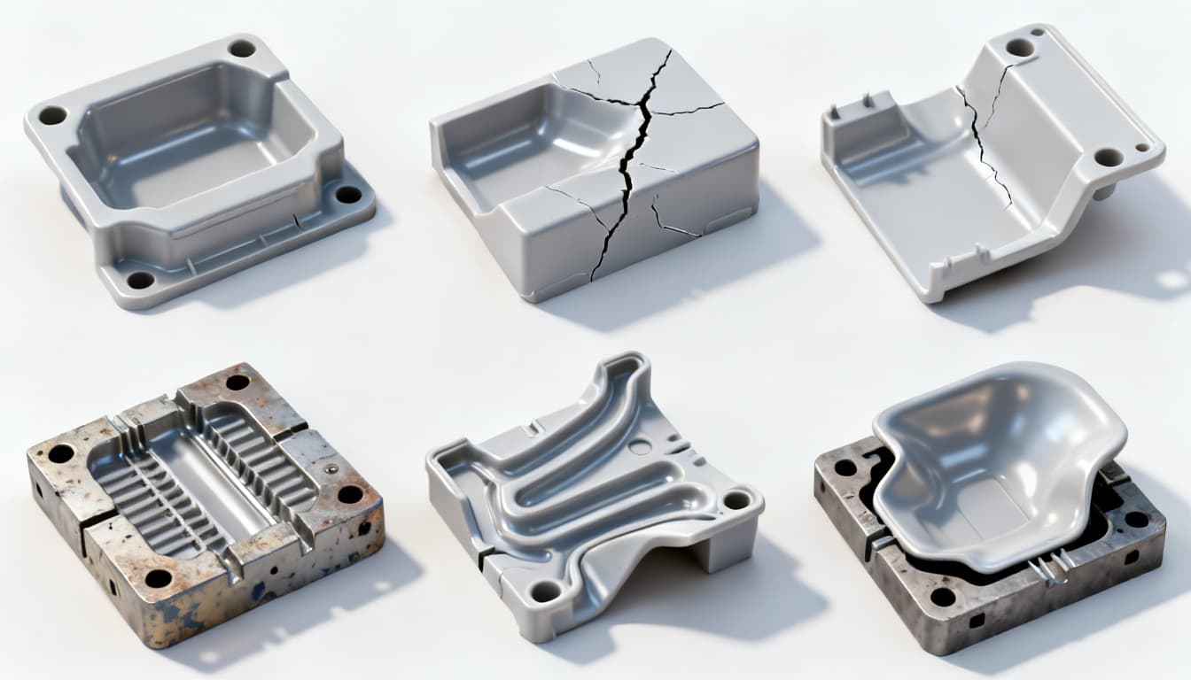
7 Design Mistakes That Ruin Plastic Injection Molded Parts (And How to Avoid Them)
It starts with a single phone call. Your molder reports that 3,000 parts from last night's run are scrap. The reason? A design feature you approved six weeks ago—something as minor as a sharp internal corner or a wall section 0.5 mm too thick—has triggered sink marks deep enough to fail cosmetic ins
Why a $0.50 Part Can Kill a Production Run: The Hidden Cost of Design Oversights
It starts with a single phone call. Your molder reports that 3,000 parts from last night's run are scrap. The reason? A design feature you approved six weeks ago—something as minor as a sharp internal corner or a wall section 0.5 mm too thick—has triggered sink marks deep enough to fail cosmetic inspection. The per-part cost was negligible. The production delay, rework, and tool modification bill are anything but.
This scenario plays out more often than most product teams admit. According to SyBridge Technologies, injection molding defects frequently trace back to poor design decisions made long before tool steel is cut—decisions that cascade into production process mistakes, quality control failures, and extended lead times (SyBridge, 2024). The 3ERP team catalogs 22 distinct injection molding defects, many of which originate not on the production floor but in the CAD file (3ERP).
Consider the case documented by PlastFabWorks: a batch of polycarbonate detergent container lids came back from the field with mysterious fractures. The investigation revealed that the polycarbonate was reacting with detergent chemicals, leading to stress-induced fractures—a material selection oversight compounded by design features that concentrated stress at the thread roots (PlastFabWorks). The lids themselves cost pennies. The recall and tooling rework cost tens of thousands.
When parts must perform in extreme environments—under chemical exposure, thermal cycling, or sustained mechanical load—the margin for design error shrinks dramatically. RMC Plastics emphasizes that poor design decisions shorten part lifespan and increase costs precisely when reliability matters most (RMC Plastics). A gasket that relaxes at 85°C, a snap-fit that embrittles at -20°C, a boss that cracks after 500 cycles—these failures are designed in, not manufactured in.
Key Takeaway: Design for Manufacturability (DFM) is not a box to check before tooling release. It is the single highest-leverage activity in the injection molding development cycle. The cost of catching a design mistake increases by roughly an order of magnitude at each stage: CAD change ($100), tool modification ($1,000–$5,000), production scrap ($10,000+), field failure (unbounded).
This article walks through the seven most common and costly design oversights we see at PandaMolding—and, more importantly, how to fix each one before your mold is cut.
The Physics of Plastic Flow: Why Wall Thickness and Draft Angles Dictate Part Quality
Injection molding is, at its core, a heat transfer problem with a deadline. Molten polymer is forced into a cavity under high pressure, then must cool uniformly enough to eject as a dimensionally stable solid. Every design decision you make—wall thickness, draft angle, corner radius, rib geometry—either helps or hinders that thermal balancing act.
When plastic flows into a mold cavity, it immediately begins losing heat to the tool steel walls. A thin section (say, 1.0 mm) solidifies in under a second. A thick section (4.0 mm) may take 15–20 seconds to freeze completely. During that time, the material shrinks as it crystallizes or cools through its glass transition. If adjacent sections cool at different rates, differential shrinkage creates internal stresses that manifest as warp, sink marks, or voids (Fictiv Design Guide).
The RTP Company's part design guidelines distill decades of application engineering into a few non-negotiable rules: maintain uniform wall thickness throughout the part, use generous radii at all internal corners, and never skip draft (RTP Company). These are not suggestions. They are the difference between a part that ejects cleanly every cycle and one that hangs up, drags, or warps unpredictably.
Quick-Reference Wall Thickness and Draft Guidelines by Material
| Thermoplastic | Recommended Wall Thickness (mm) | Minimum Draft Angle (per side) | Shrinkage Range (%) | Notes |
|---|---|---|---|---|
| ABS | 1.0 – 3.5 | 0.5° – 1.0° | 0.4 – 0.7 | Forgiving flow; good for complex geometries |
| Polycarbonate (PC) | 1.0 – 3.8 | 0.5° – 1.0° | 0.5 – 0.7 | Higher viscosity; needs generous gates |
| Polypropylene (PP) | 0.8 – 3.8 | 1.0° – 1.5° | 1.0 – 2.5 | High shrinkage; uniform walls critical |
| Nylon 6/6 (PA 66) | 0.8 – 3.0 | 0.5° – 1.0° | 1.0 – 2.0 | Moisture-sensitive; design for conditioning |
| POM (Acetal) | 0.8 – 3.0 | 0.5° – 1.0° | 1.8 – 2.5 | High shrinkage; avoid thick sections |
| PBT | 0.8 – 3.0 | 0.5° – 1.0° | 1.5 – 2.0 | Fast crystallization; watch gate freeze |
| TPE/TPU | 1.0 – 3.0 | 1.5° – 3.0° | 1.0 – 3.0 | Flexible; higher draft needed for ejection |
| PC/ABS Blend | 1.0 – 3.5 | 0.5° – 1.0° | 0.5 – 0.7 | Balanced properties; good flow |
These ranges are starting points. Textured surfaces demand additional draft—typically 1.5° to 3° per side for light grain textures, and up to 5° for heavy leather or stipple patterns. Insufficient draft on a textured surface produces drag marks (visible white streaks) and can cause the part to stick in the cavity, damaging both the part and the mold with each ejection cycle.
Tip: If your design absolutely requires a thick section adjacent to a thin one, use a gradual transition zone with a slope no steeper than 3:1 (length-to-thickness ratio). Abrupt step changes in wall thickness are among the most reliable ways to generate sink marks and internal voids.
Amorphous vs. Semi-Crystalline Resins: How Material Choice Shapes Your Design Rules
Selecting a polymer is not just a material properties decision—it is a design rules decision. The two broad families of thermoplastics, amorphous and semi-crystalline, behave fundamentally differently during molding, and a design optimized for one family may fail spectacularly with the other.
Amorphous polymers (ABS, polycarbonate, polystyrene, acrylic) have a random molecular structure. They soften gradually over a temperature range rather than melting at a discrete point. This gives them lower and more predictable shrinkage (typically 0.4–0.7%), excellent dimensional stability, and better transparency. However, they have poorer chemical resistance and can be prone to stress cracking when exposed to certain solvents or oils.
Semi-crystalline polymers (nylon, POM, polypropylene, PBT, PEEK) have regions of ordered molecular structure interspersed with amorphous regions. They exhibit a sharp melting point, higher shrinkage (1.0–2.5% or more), and significantly better chemical resistance and fatigue performance. The design challenge: their higher and more anisotropic shrinkage makes them far less forgiving of non-uniform wall thickness (Ensinger Precision Components).
Protolabs reinforces this point: knowing your material specifications early can save enormous pain later. Thin areas cool faster than thick ones, and in semi-crystalline materials, that temperature differential creates differential crystallization—a recipe for warp that no amount of process tweaking can fully correct (Protolabs).
Amorphous vs. Semi-Crystalline: Design Rule Comparison
| Comparison Metric | Amorphous (ABS, PC, PS, Acrylic) | Semi-Crystalline (PA, POM, PP, PBT) | Selection Criteria & Failure Boundary |
|---|---|---|---|
| Shrinkage Range | 0.4 – 0.7% (low, isotropic) | 1.0 – 2.5% (higher, anisotropic) | Choose amorphous for tight-tolerance parts; semi-crystalline needs more generous tolerances |
| Wall Thickness Sensitivity | Moderate; some variation tolerated | High; non-uniform walls cause severe warp | Semi-crystalline parts demand near-perfect wall uniformity |
| Draft Angle Requirement | 0.5° – 1.0° typical | 0.5° – 1.5° (higher for PP/PE) | Softer semi-crystalline grades (PP) need more draft to prevent scuffing |
| Chemical Resistance | Poor to moderate; stress cracking risk | Excellent; suitable for fuel, oil, solvents | If chemical exposure is expected, semi-crystalline is usually mandatory |
| Transparency | Excellent (PC, acrylic, PS) | Poor (translucent at best unless nucleated) | Optical parts almost always use amorphous resins |
| Fatigue & Wear Resistance | Moderate | Excellent (especially POM, PA) | Living hinges, gears, and bearings favor semi-crystalline |
| Mold Temperature Sensitivity | Moderate; wider process window | Critical; mold temp controls crystallinity | Semi-crystalline parts need tighter process control for consistent properties |
The practical implication: if you are designing a snap-fit housing for an indoor consumer device, ABS (amorphous) gives you a forgiving process window and predictable dimensions. If that same housing must survive under-hood automotive temperatures and chemical exposure, you are likely moving to a glass-filled nylon (semi-crystalline)—and you need to redesign your wall thicknesses, draft angles, and gating strategy accordingly. The material choice ripples through every dimension on your drawing.
The 7 Most Costly Design Oversights—and How to Fix Them Before Tooling
Drawing on field experience at PandaMolding and insights from across the injection molding industry, here are the seven design mistakes we see most frequently—and the practical fixes that prevent them from reaching the production floor (Ensinger) (Protolabs) (Protoshop) (BeraTek Industries).
Mistake 1: Sharp Internal Corners
The problem: A 90-degree internal corner concentrates stress at a single point. Under load or during ejection, cracks initiate at that corner. This is the single most common cause of field failures in structural plastic parts.
The fix: Apply a radius to every internal corner. The minimum recommended radius is 0.5 mm, but ideally 25–50% of the adjacent wall thickness. A 3 mm wall should have at least a 0.75 mm internal radius. This distributes stress and improves material flow during filling.
Mistake 2: Non-Uniform Wall Thickness
The problem: Thick sections cool slowly, thin sections cool quickly. The resulting differential shrinkage creates sink marks on cosmetic surfaces and internal voids that compromise structural integrity. This is especially severe in semi-crystalline materials like polypropylene and nylon.
The fix: Design for uniform nominal wall thickness throughout the part. Where a thicker section is unavoidable (e.g., at a boss or rib base), keep the thickness ratio below 3:1 and use a gradual transition. Core out thick sections from the back side to maintain a consistent wall.
Mistake 3: Inadequate or Missing Draft
The problem: Vertical walls without draft create friction during ejection. Parts stick, drag, or require excessive ejection force that distorts the part while it is still hot. Textured surfaces without adequate draft are particularly problematic.
The fix: Apply a minimum of 0.5° draft on all vertical surfaces, increasing to 1.5°–3° for light textures and up to 5° for heavy grain. Draft should be added to the part design, not left for the mold maker to interpret.
Mistake 4: Poor Gate Location
The problem: The gate is where molten plastic enters the cavity. A poorly placed gate creates weld lines in structurally critical areas, traps air, or causes uneven filling that leads to warp. Gate location also determines the orientation of glass fibers, which directly affects part strength.
The fix: Use mold flow analysis to optimize gate placement before cutting steel. Position gates away from cosmetic surfaces and high-stress areas. For fiber-filled materials, place gates to orient fibers along the primary load path.
Mistake 5: Overly Deep Ribs and Undersized Bosses
The problem: Ribs that are too tall relative to their base thickness create filling difficulties and ejection challenges. Bosses with insufficient wall thickness crack during screw insertion or strip out under torque.
The fix: Keep rib height to no more than 3× the nominal wall thickness. Rib base thickness should be 50–60% of the adjacent wall. Boss outer diameter should be 2× the screw diameter, with a wall thickness of 60–80% of the nominal wall. Use gussets to reinforce tall bosses.
Mistake 6: Ignoring Material-Specific Design Constraints
The problem: A design that works beautifully in ABS may fail in glass-filled nylon. Each polymer family has unique constraints: polycarbonate needs generous radii to avoid stress cracking, acetal hates thick sections due to high shrinkage, and TPEs need significantly more draft than rigid materials.
The fix: Finalize your material selection before completing the part design. Consult the resin supplier's design guide for specific recommendations on wall thickness, draft, radii, and gating. Do not assume a design is material-agnostic.
Mistake 7: Designing Without Mold Flow Analysis
The problem: CAD software will happily model a part that is impossible to fill, pack, or cool uniformly. Without simulation, you discover filling problems when the first shots come off the press—at which point tool modifications are expensive and schedule-killing.
The fix: Request a mold flow analysis as part of your DFM review. A proper analysis predicts fill patterns, weld line locations, air traps, sink mark severity, and warpage tendencies. The cost (typically $500–$1,500) is trivial compared to the cost of re-cutting a mold (Upmold).
Design Mistake Summary and Corrective Actions
| Design Mistake | Typical Consequence | Prevention Strategy | Detection Method |
|---|---|---|---|
| Sharp internal corners | Stress cracking, premature failure | Minimum 0.5 mm radius; 25–50% of wall thickness | CAD review; FEA stress analysis |
| Non-uniform wall thickness | Sink marks, voids, warpage | Uniform nominal wall; 3:1 max transition ratio | Section analysis in CAD; mold flow simulation |
| Inadequate draft | Drag marks, ejection difficulty | 0.5° min; 1.5°–5° for textured surfaces | Draft analysis tool in CAD |
| Poor gate location | Weld lines, air traps, warp | Mold flow analysis; gate away from cosmetics | Mold flow simulation |
| Overly deep ribs / undersized bosses | Fill issues, cracking, thread stripping | Rib height ≤ 3× wall; boss OD = 2× screw dia. | CAD review against material design guide |
| Material-agnostic design | Unexpected shrinkage, warpage, failure | Finalize material before design; consult supplier guide | Material-specific DFM checklist |
| No mold flow analysis | Tool rework, production delays | Require mold flow as DFM deliverable | Simulation report review |
Each of these mistakes is preventable with disciplined DFM review. The common thread: the earlier you catch the issue, the cheaper it is to fix. BeraTek Industries puts it bluntly: designing for injection molding is not just an engineering exercise—it is a cost decision, a timeline decision, and often the difference between a smooth product launch and months of unexpected setbacks (BeraTek Industries).
Questions Engineers Ask Before Signing Off on a Mold Design
Every project lead reaches a moment where they must approve a mold design for cutting. These are the questions we hear most often at PandaMolding—and the answers that help you make that decision with confidence (Firstmold Quality Standards) (Upmold Specifications).
Q: How much draft is really necessary for a textured surface?
For light textures (SPI/SPE grades D-1, D-2, or equivalent fine grain), plan for 1.5° to 3° of draft per side. Medium textures (leather grain, moderate stipple) typically require 3° to 4°. Heavy textures and deep undercuts may need 5° or more. The rule of thumb: add 1° of draft for every 0.025 mm (0.001 inch) of texture depth. Insufficient draft on a textured surface produces visible drag marks—white streaks where the texture has been scraped during ejection—and can cause the part to stick in the cavity, damaging both the part surface and the mold texture with each cycle.
Q: When is it acceptable to have non-uniform wall thickness?
Non-uniform walls are acceptable only when the transition between thicknesses is gradual and the part function genuinely demands it. The maximum recommended transition ratio is 3:1—meaning a 3 mm thick section should taper to a 1 mm section over a distance of at least 6 mm. Abrupt step changes in wall thickness are never acceptable; they create localized hot spots that cool slowly, producing sink marks on the opposite surface and internal voids that act as stress concentrators. If your design requires a thick boss or mounting pad, core it out from the back side to maintain a consistent nominal wall.
Q: What is the cost impact of changing a design after the mold is cut?
Steel-safe modifications—changes that involve removing material from the mold (making the plastic part larger)—typically cost $1,000 to $5,000 depending on complexity and require one to three weeks of downtime. Changes that require adding material to the mold (making the plastic part smaller) are far more expensive because they may involve welding and re-machining, or in severe cases, replacing an entire cavity insert. A major design change after tooling can effectively double your tooling investment. This is why mold flow analysis and thorough DFM review before steel cutting are among the highest-return activities in the entire development process.
Q: How do I specify acceptable sink marks on a cosmetic surface?
Define a quantitative sink mark depth limit on your part drawing—typically 0.05 mm (0.002 inch) for high-visibility Class A surfaces, and up to 0.10 mm (0.004 inch) for less critical areas. Reference the SPI/SPE surface finish standard to establish the cosmetic grade. A practical strategy: specify a light texture (SPI D-2 or equivalent) on surfaces opposite ribs and bosses; the texture disrupts light reflection and makes minor sink marks visually undetectable. Your molder can also use gas-assisted molding or conformal cooling in critical areas to minimize sink, though these add tooling cost.
Q: Can I use the same design for both prototype and production molds?
Not without adjustments. Prototype molds are typically machined from aluminum and use different cooling strategies than production steel molds. Aluminum conducts heat differently, which affects cycle time, shrinkage, and part dimensions. Gate locations optimized for an aluminum prototype mold may produce different fill patterns in a production steel mold due to thermal differences. You should plan for at least one design iteration between prototype and production tooling to account for these differences. At minimum, re-run mold flow analysis with production mold thermal parameters before committing to steel.
Q: What documentation should I request from my molder to verify DFM compliance?
Three documents form the core of DFM verification: (1) a mold flow analysis report showing fill time, pressure distribution, weld line locations, air trap predictions, sink mark depth estimates, and warpage simulation; (2) a dimensional capability study demonstrating that the mold can hold the specified tolerances (typically a CpK ≥ 1.33 for critical dimensions); and (3) a first article inspection (FAI) report that measures every dimension on the first production samples against your CAD model. For regulated industries, you may also need material certification, process parameter documentation, and a production part approval process (PPAP) package.