A Practical Step-by-Step Guide to Mold Cooling Channel Design: From Simulation to Steel
Cooling typically consumes up to 70% of the injection molding cycle—a figure that surprises many engineers until they examine their own process data. When you're running a multi-cavity tool at thousands of cycles per month, every second of cooling time translates directly into throughput, margin, an
The 70% Factor: Why Cooling Channel Design Drives Cycle Time and Part Quality
Cooling typically consumes up to 70% of the injection molding cycle—a figure that surprises many engineers until they examine their own process data. When you're running a multi-cavity tool at thousands of cycles per month, every second of cooling time translates directly into throughput, margin, and delivery performance. Poor cooling channel design doesn't just extend cycle time; it introduces differential shrinkage, warpage, sink marks, and dimensional instability that no amount of process tweaking can fully correct.
The physics is straightforward: molten polymer enters the cavity at 200–300°C (depending on the resin), and the part must be ejected below its heat deflection temperature. The mold steel acts as a heat exchanger, and the cooling channels are the working fluid's pathway to carry that thermal energy away. When channels are placed too far from the cavity surface, spaced inconsistently, or sized without regard for flow turbulence, you get hot spots. Hot spots mean non-uniform cooling, and non-uniform cooling means warped parts.
Key Takeaway: Cooling channel design is not a secondary consideration to be addressed after the cavity geometry is finalized. It is a primary determinant of part quality and cycle economics. As Stebro Mold's comprehensive design guide notes, efficient cooling optimization directly reduces cycle time, improves dimensional stability, and lowers per-part cost—benefits that compound dramatically over production volumes reaching hundreds of thousands or millions of cycles.
Simulation has transformed how we approach this challenge. Rather than relying on rules of thumb and hoping the tool runs right on the first shot, engineers can now evaluate temperature profiles and cooling time virtually before any steel is cut. Manufyn's design guide emphasizes that simulation-based validation reduces tooling iterations, shortens lead time, and improves first-time-right production outcomes—a claim backed by shops that have moved away from trial-and-error mold tuning. When you can see the thermal map of your mold in software, you make decisions with confidence rather than crossing your fingers during the first sampling run.
The cost of getting cooling wrong shows up in ways that aren't always obvious on the P&L: extended cycle times that erode margin, elevated scrap rates from warpage, and tooling rework that delays product launches. For buyers sourcing injection molds, specifying cooling channel design requirements upfront—and verifying them through simulation reports—is one of the highest-ROI activities in the entire procurement process.
How Cooling Channels Work: Thermal Principles and Key Design Parameters
At its core, a mold cooling channel is a heat exchanger passage. Coolant (typically water or a water-glycol mixture) flows through drilled or additively manufactured channels, absorbing heat conducted through the mold steel from the polymer melt. The efficiency of this heat transfer depends on several interdependent parameters that every mold designer must balance.
The Reynolds number (Re) is the starting point for any cooling design. It quantifies whether your coolant flow is laminar or turbulent. Turbulent flow (typically Re > 4,000–5,000) dramatically improves heat transfer because the mixing action continuously brings fresh, cool fluid into contact with the channel wall. Laminar flow creates a insulating boundary layer that reduces cooling efficiency. Achieving turbulent flow means specifying adequate coolant flow rates and channel diameters—a calculation that should be performed for every circuit, not assumed.
Channel diameter typically ranges from 7/16″ to 9/16″ (approximately 11–14 mm) for most production molds, though smaller diameters down to 1/4″ (6.35 mm) appear in tight spaces. Larger diameters reduce pressure drop but require higher flow rates to maintain turbulence. Channel spacing (pitch) and distance from the cavity surface follow the well-established guideline that channels should be placed at a depth of 1.5–2.5 times the channel diameter from the cavity wall, with center-to-center spacing of 3–5 times the diameter. Tighter spacing improves cooling uniformity but increases manufacturing cost and the risk of intersecting other mold features.
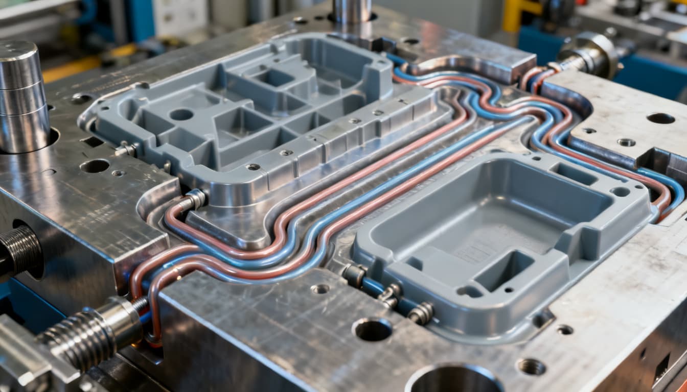
As MoldMaking Technology emphasizes, cooling circuit optimization begins with channels that mirror the shape of the mold cavity, enabling rapid and uniform heat extraction. This principle—that the cooling circuit should follow the part contour—is what separates adequate cooling from truly optimized thermal management. Straight drilled channels can approximate this for simple geometries, but complex parts demand more sophisticated approaches.
AIM Processing's design guide reinforces that the goal is a uniform temperature profile around the plastic part, achieved through deliberate channel placement and simulation-driven iteration. The options and recommendations they present form a practical framework that balances thermal performance with manufacturability and cost.
| Material | Thermal Conductivity (W/m·K) | Typical Hardness | Best Application | Trade-off Notes |
|---|---|---|---|---|
| P20 Tool Steel | 29–34 | 28–32 HRC | General-purpose production molds; moderate volumes | Good balance of machinability and wear resistance; lower conductivity limits cooling speed |
| H13 Tool Steel | 24–28 | 46–52 HRC | High-temperature resins; abrasive materials; high-volume production | Excellent hot hardness and wear resistance; lowest thermal conductivity in this group |
| 420 Stainless Steel | 23–26 | 48–52 HRC | Corrosion-resistant applications; medical and food-contact parts | Corrosion resistance comes at the cost of thermal conductivity; requires careful cooling design |
| QC-10 Aluminum (AlZnMgCu) | 150–170 | ~150 HB | Prototype molds; low-to-medium volume; fast-cycle applications | 4–10× the conductivity of steel; significantly lower wear resistance limits high-volume use |
| CuBe (Beryllium Copper) | 105–130 | 30–42 HRC | Insert materials for hot spots; core pins; areas needing rapid heat removal | Excellent conductivity with moderate hardness; higher material cost; beryllium requires safety protocols during machining |
The conductivity gap between aluminum and steel is substantial—aluminum moves heat four to ten times faster. This makes aluminum an attractive option for prototype tooling and low-to-medium volume production where cycle time is the dominant concern. However, as production volumes climb and abrasive materials enter the picture, steel's wear resistance becomes non-negotiable. The decision isn't simply about thermal performance; it's about the total cost of ownership across the tool's expected lifespan.
Tip: When specifying mold materials, always document the steel grade, hardness, and finish on the final mold design—a practice KAM Plastics' mold standards identify as essential for ensuring the tool meets both thermal and mechanical requirements over its service life.
Conventional vs. Conformal Cooling: Choosing the Right Channel Strategy
For decades, mold cooling channels were exclusively straight, drilled passages—intersecting lines created by gun-drilling through the mold plates. This method is well-understood, relatively inexpensive, and perfectly adequate for parts with simple, planar geometries. But as part complexity increases, the limitations of straight-line cooling become apparent: areas far from drilled channels run hot, while regions near channels cool faster. The result is differential shrinkage and warpage.
Conformal cooling channels (CCC) represent a paradigm shift. Produced through additive manufacturing—typically direct metal laser sintering (DMLS) or selective laser melting (SLM)—conformal channels follow the three-dimensional contour of the cavity surface. They maintain a consistent distance from the part regardless of geometry complexity, delivering uniform heat extraction that straight channels simply cannot match.
The performance data is compelling. Research published in PMC (Polymers) demonstrated that conformal cooling channels reduced final part warpage by 32.4% in metal molds and by 59.8% in polymer molds when compared to conventional straight-channel designs. These aren't marginal improvements—they represent the difference between parts that meet dimensional specifications and parts that require secondary operations or end up as scrap.
Simulation tools have evolved to support both channel types. SimForm's thermal analysis workflow provides a step-by-step process for evaluating mold designs with conventional or conformal cooling channels, allowing designers to compare strategies before committing to manufacturing. This capability is particularly valuable when weighing the higher upfront cost of additive manufacturing against the cycle time and quality benefits of conformal cooling.
| Comparison Metric | Conventional Drilled Channels | Conformal Cooling Channels (CCC) | Selection Criteria & Failure Boundary |
|---|---|---|---|
| Manufacturing Method | Gun-drilling; standard machining | Additive manufacturing (DMLS/SLM); hybrid machining | Choose conventional when geometry permits straight-line access; choose CCC when part contours demand 3D channel paths |
| Geometry Flexibility | Limited to straight lines and intersecting bores | Full 3D contour-following capability; variable cross-sections possible | Parts with deep cores, complex curvature, or varying wall thickness benefit most from CCC |
| Cooling Uniformity | Variable; hot spots common in complex geometries | Highly uniform; consistent distance from cavity surface | Warpage-sensitive parts (tight tolerances, thin walls) justify CCC investment |
| Typical Warpage Reduction | Baseline | 32.4% reduction in metal molds; 59.8% in polymer molds (per PMC research) | Calculate scrap cost savings vs. CCC tooling premium over projected production volume |
| Tooling Cost | Lower; standard mold shop capabilities | Higher; requires AM equipment and post-processing; 20–50% premium typical | High-volume production (>100k cycles) often amortizes CCC premium through cycle time savings |
| Lead Time | Shorter; established supply chain | Longer; AM build time plus finish machining | Factor lead time into launch schedule; CCC may be impractical for rush programs |
| Maintenance & Cleaning | Straight channels easy to clean and inspect | Complex paths require specialized cleaning; risk of blockage if coolant quality is poor | Implement rigorous coolant filtration and periodic flow testing for CCC molds |
The choice between conventional and conformal cooling isn't binary—many production molds use a hybrid approach. Conformal inserts are placed in thermally challenging areas (deep cores, thick sections, tight radii) while the surrounding mold base uses conventional drilled channels. This strategy captures most of the thermal benefit while controlling the additive manufacturing cost. Manufyn's approach of using simulation early in the DFM process helps identify exactly where conformal cooling adds value, preventing over-engineering while ensuring critical areas receive adequate thermal management.
Note: The 59.8% warpage reduction in polymer molds (from the PMC study) is particularly relevant for bridge tooling and low-volume production where aluminum or polymer mold inserts are used. The thermal conductivity advantage of these materials combines synergistically with conformal channel geometry to produce exceptional cooling uniformity.
From Simulation to Steel: A Step-by-Step Workflow for Optimizing Cooling Channels
Moving from a part model to an optimized, production-ready cooling design requires a disciplined workflow. The following process has been refined through hundreds of mold builds and reflects the integration of modern simulation tools with practical mold-making constraints.
Step 1: Define Cooling Requirements. Start with the resin datasheet. Every polymer has a recommended mold temperature range, melt temperature, and ejection temperature. Calculate the theoretical heat load based on shot weight, cycle time target, and material-specific enthalpy. This gives you the total heat removal requirement (in watts or BTU/hr) that your cooling system must handle. Document these numbers—they become your design targets and verification criteria.
Step 2: Model the Initial Channel Layout. Using your CAD system, place channels following the cavity contour as closely as practical. Apply the 1.5–2.5× diameter rule for cavity-to-channel distance and 3–5× diameter for channel spacing. For complex parts, identify regions where straight channels cannot maintain adequate proximity to the cavity surface—these are your candidates for conformal cooling or auxiliary cooling devices (baffles, bubblers, thermal pins).
Step 3: Run Thermal Simulation. Import your channel layout into simulation software. SimForm's thermal analysis workflow provides a structured approach for evaluating both conventional and conformal designs. Alternatively, Autodesk Moldflow, Moldex3D, and Sigmasoft offer robust cooling analysis modules. The simulation should output: cavity surface temperature distribution, coolant temperature rise across each circuit, heat removal rate per circuit, and time to reach ejection temperature. Pay particular attention to the temperature range across the cavity surface—a spread of more than 5–10°C indicates potential warpage risk.
Step 4: Interpret Results and Iterate. Hot spots visible in the simulation are your priority targets. Adjust channel positions, add circuits, or convert problematic regions to conformal geometry. Re-run the simulation after each significant change. The goal is not perfection on the first iteration but systematic convergence toward uniform cooling. Three to five simulation cycles are typical for complex parts, and this time investment pays for itself many times over by preventing tool rework.
Step 5: Finalize the Mold Design with Complete Documentation. Once simulation confirms acceptable cooling uniformity and cycle time, lock the design. Per KAM Plastics' mold standards, the final mold design must specify: all materials used, the shrink factor to which the tool is built, hardness of each steel component, and required surface finishes. For cooling channels specifically, document: channel diameters, circuit routing, coolant type and flow rate requirements, and Reynolds number targets. This documentation protects both the mold buyer and the mold maker by establishing clear performance expectations before steel is cut.
Step 6: Verify During Sampling. The first shots off the tool should be accompanied by thermal imaging or contact thermometry to validate that actual mold temperatures match simulation predictions. Any significant deviation warrants investigation before the mold enters full production. This verification step closes the loop between simulation and reality, building organizational knowledge that improves future designs.
| Design Parameter | Recommended Value/Range | Unit/Notes | Verification Method |
|---|---|---|---|
| Channel Diameter | 7/16″–9/16″ (11–14 mm) standard; 1/4″ (6.35 mm) minimum for tight spaces | inches / mm | CAD measurement; pin gauge during inspection |
| Cavity-to-Channel Distance | 1.5–2.5 × channel diameter | Dimensionless multiplier | CAD measurement; simulation temperature map |
| Channel Center-to-Center Spacing | 3–5 × channel diameter | Dimensionless multiplier | CAD measurement; simulation uniformity check |
| Reynolds Number (Target) | >5,000 for turbulent flow; 10,000+ ideal | Dimensionless | Calculated from flow rate, diameter, coolant properties |
| Coolant Flow Rate | 3–5 GPM per circuit (typical); adjust for diameter and Re target | GPM / L/min | Flow meter during mold setup; pressure drop measurement |
| Coolant Temperature Rise (ΔT) | ≤2–3°C across circuit | °C / °F | Inlet/outlet thermocouples; simulation validation |
| Mold Surface Temperature Uniformity | ≤5–10°C variation across cavity | °C | Thermal imaging during sampling; simulation correlation |
| Circuit Pressure Drop | <30 PSI per circuit (typical target) | PSI / bar | Pressure gauge at mold inlet/outlet |
These parameters are not independent—changing channel diameter affects Reynolds number, pressure drop, and the achievable cavity-to-channel distance simultaneously. Simulation handles these interdependencies automatically, which is why it has become indispensable. A manual calculation can verify individual circuits, but only simulation can show you how all circuits interact across the entire mold geometry.
Tip: When documenting the mold design, include simulation screenshots showing the predicted temperature distribution. These images communicate cooling strategy more effectively than drawings alone and serve as a reference during production troubleshooting.
Cooling Channel Design FAQs for Engineers and Buyers
Q: How much cycle time reduction can I realistically expect from optimized cooling channels?
Cooling typically accounts for up to 70% of the injection molding cycle, so improvements in this phase have outsized impact. Optimized cooling channel designs—whether through better conventional channel placement or conformal cooling—can reduce cooling time by 30–50% compared to poorly designed or rule-of-thumb layouts. On a 30-second cycle where cooling consumes 20 seconds, a 40% cooling time reduction frees up 8 seconds per cycle. Over 500,000 cycles annually, that's over 1,100 hours of recovered production capacity. The exact savings depend on part geometry, wall thickness, and material, but double-digit percentage reductions in overall cycle time are consistently achievable with simulation-driven cooling design.
Q: When should I invest in conformal cooling over conventional drilled channels?
Conformal cooling justifies its higher tooling cost in three scenarios. First, complex part geometries where straight channels cannot maintain consistent distance from the cavity surface—deep cores, curved surfaces, and parts with significant thickness variation are prime candidates. Second, high warpage risk parts where dimensional stability is critical and the cost of scrap or secondary operations exceeds the conformal cooling premium. Third, high-volume production where even a 2–3 second cycle time reduction generates substantial annual savings. A simple ROI calculation: multiply the expected cycle time savings by your machine hour rate and annual production volume, then compare to the conformal cooling tooling premium. If payback occurs within 6–12 months of production, conformal cooling is typically the right choice.
Q: What simulation tools are commonly used for mold cooling analysis?
Industry-standard tools include Autodesk Moldflow (widely adopted, comprehensive cooling analysis with conformal channel support), Moldex3D (strong 3D meshing capabilities and specialized cooling modules), Sigmasoft (known for detailed thermal analysis and virtual molding), and SimForm (accessible thermal analysis with dedicated workflows for both conventional and conformal cooling evaluation). Most of these tools integrate with major CAD platforms and offer specialized modules for cooling channel design. The choice often depends on your existing software ecosystem, the complexity of your typical parts, and whether you need standalone cooling analysis or full injection molding simulation. For buyers evaluating mold suppliers, requesting simulation reports from any of these platforms provides a meaningful basis for comparing cooling design quality across vendors.
Q: What are the key parameters to specify in a mold design for cooling channels?
Critical parameters include: channel diameter (typically 7/16″–9/16″ for production molds), channel spacing (center-to-center distance of 3–5× diameter), distance from the cavity surface (1.5–2.5× diameter), coolant flow rate per circuit (sufficient to achieve turbulent flow with Reynolds number >5,000), coolant type and supply temperature, and circuit layout including the number of independent circuits. These parameters should be documented on the mold design and verified during sampling. The specification should also include the target mold surface temperature uniformity (typically ≤5–10°C variation across the cavity) and maximum allowable coolant temperature rise per circuit (≤2–3°C).
Q: How do I ensure uniform cooling across a large or complex part?
Uniform cooling of large or complex parts requires breaking the cooling system into multiple independent circuits, each serving a specific region of the cavity. Use baffles and bubblers in deep cores where drilled channels cannot reach. For parts with significant contour variation, conformal cooling channels that follow the part surface at a consistent offset distance provide the most uniform heat extraction. Simulation is essential—it reveals hot spots that would otherwise go undetected until production sampling, and it allows you to balance flow rates across circuits to achieve uniform temperature distribution. Thermal imaging during sampling provides the final verification that your multi-circuit strategy is working as intended.
Q: What are the trade-offs between aluminum and steel molds for cooling efficiency?
Aluminum offers 4–10× the thermal conductivity of steel (150–170 W/m·K for QC-10 aluminum vs. 24–34 W/m·K for common tool steels), enabling significantly faster heat extraction and shorter cycle times. This makes aluminum attractive for prototype tooling, bridge production, and applications where cycle time dominates the economic equation. However, aluminum's lower hardness (approximately 150 HB vs. 28–52 HRC for tool steels) limits its wear resistance, making it less suitable for abrasive materials (glass-filled resins, engineering polymers with abrasive additives) and high-volume production beyond roughly 100,000 cycles. Steel's superior wear resistance and hot hardness make it the default choice for production tooling, with the cooling efficiency gap addressed through optimized channel design and, where necessary, conformal cooling or high-conductivity insert materials like beryllium copper in hot spot locations. The decision should weigh total cost of ownership—including tool life, maintenance, and cycle time—against the specific production volume and material requirements of your program.
References & Further Reading
- Stebro Mold — Injection Mold Cooling Systems: Design Principles
- Manufyn — Mold Cooling Channel Design: Reduce Cycle Time & Warpage
- AIM Processing — Designing Cooling Channels in Injection Molds: A Combination of Art and Science
- SimForm — Mold Cooling Thermal Analysis Using Basic Channels
- PMC (Polymers) — Evaluating the Cooling Efficiency of Polymer Injection Molds by Computer Simulation Using Conformal Channels
- KAM Plastics Corp. — Mold Standards and Specifications
- MoldMaking Technology — The Mold Specification Document, Part 3 of 4
- Plastics Technology — Injection Molding Knowledge Center
Effective cooling channel design is one of the highest-leverage