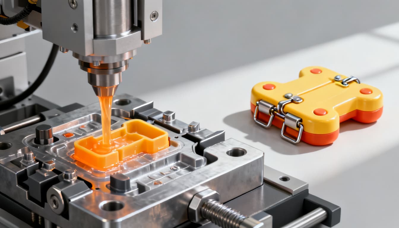
A Step-by-Step Guide to Injection Molding Toys with Insert Molding and Living Hinges for Durability
Every product engineer who has designed a toy knows the sinking feeling: a hinge snaps during testing, a metal axle pulls free from a plastic socket, or a joint that worked perfectly in prototype form fails after a hundred flex cycles in a child's hands. These failures aren't just frustrating—they'r
The Million-Cycle Secret Behind Unbreakable Toy Joints
Every product engineer who has designed a toy knows the sinking feeling: a hinge snaps during testing, a metal axle pulls free from a plastic socket, or a joint that worked perfectly in prototype form fails after a hundred flex cycles in a child's hands. These failures aren't just frustrating—they're expensive. Returns pile up, brand reputation suffers, and redesign cycles eat into margins that were already tight.
The root cause is almost always the same: treating the joint as an assembly problem rather than a molding problem. When you bolt, snap, or press-fit components together after molding, you introduce stress concentrations, tolerance stack-ups, and assembly labor costs that compound across thousands of units. There's a better way—two techniques that have been quietly producing nearly unbreakable toys for decades: living hinges and insert molding.
A living hinge is a thin, flexible web of plastic molded directly between two rigid segments of a part. When designed correctly, it can flex hundreds of thousands—even millions—of times without failure. Protolabs' research on living hinge design confirms that a well-executed polypropylene living hinge can endure up to a million cycles. That's not marketing hyperbole; it's a material property rooted in polypropylene's unique ability to orient its molecular chains along the hinge line during flow, creating a self-reinforcing structure that actually strengthens with initial use.
Insert molding takes the concept further. Instead of molding plastic parts and then assembling metal axles, threaded inserts, or reinforcement pins as a secondary operation, you place those metal components directly into the mold cavity before injection. The molten plastic flows around them, encapsulating the insert and creating a bond that is mechanically locked—not just friction-fit. The result is a toy truck wheel that won't pull off its axle, an action figure limb that won't separate at the joint, or a container latch that survives being stepped on.
Toy manufacturers who adopt these techniques early in the design phase eliminate entire assembly lines, reduce part counts by 40–60%, and produce products that earn genuine durability reputations. The million-cycle hinge isn't a theoretical ideal—it's an achievable specification when you control material selection, gate placement, and hinge geometry simultaneously. This guide walks you through exactly how to do that, from pellet selection to production tooling.
From Pellets to Play: How Injection Molding Creates Living Hinges and Embeds Inserts
The process of molding a toy part that combines a living hinge with an insert-molded metal component follows a precise sequence. Understanding each step helps you anticipate where defects originate and how to prevent them before cutting steel.
Step-by-Step Process Overview
- Material preparation: Polypropylene pellets (the dominant living-hinge material) are dried to manufacturer specifications—typically 2–4 hours at 80°C for hygroscopic grades, though many PP grades require minimal drying. The metal inserts—whether brass threaded nuts, steel axles, or custom-machined pins—are cleaned and, critically, preheated to 80–120°C to reduce thermal shock when molten plastic at 200–250°C contacts them.
- Insert loading: The preheated insert is placed into the mold cavity. For low-to-medium volumes (under 50,000 units/year), this is often done manually by an operator between cycles. For higher volumes, automated pick-and-place systems or bowl feeders with escapement mechanisms load inserts consistently in under two seconds. Hubs' injection molding design guide emphasizes that insert location tolerance must be tighter than ±0.05 mm to prevent misalignment that can damage the mold during clamping.
- Mold closing and clamping: The mold closes around the insert. Hardened steel pockets or retractable pins hold the insert in position. Clamping force must account for the reduced cavity volume caused by the insert—a 50-ton press might only need 35 tons of effective clamping for an insert-molded cavity, but miscalculating this can lead to flash or incomplete filling.
- Injection and packing: This is where gate placement becomes critical. For a living hinge, the gate must be positioned so that molten polymer flows across the hinge—perpendicular to the hinge line—not parallel to it. Protolabs' molding guide explains that this orientation aligns polymer chains across the hinge's flex axis, dramatically improving fatigue resistance. Flow parallel to the hinge creates weak knit lines exactly where stress concentrates during flexing. The thin hinge section (0.25–0.5 mm) fills rapidly due to shear heating, which lowers viscosity locally and prevents short shots—provided venting is adequate.
- Cooling and solidification: The part cools for 8–20 seconds depending on wall thickness. Differential shrinkage between the plastic and the metal insert must be managed carefully. PP shrinks at 1.5–2.0% while steel shrinks negligibly, creating residual hoop stress around the insert. Preheating the insert reduces this stress, as does designing a small radius or boss around the insert to distribute shrinkage forces.
- Ejection: The mold opens and ejector pins push the part free. For living hinges, ejection must be gentle and uniform—localized force on a 0.3 mm hinge can tear it instantly. Ejector pins should contact rigid sections of the part, never the hinge itself. A polished mold surface (SPI A-2 or better) in the hinge area reduces adhesion and ejection force.
Material Selection for Living Hinges in Toys
Not all thermoplastics can form a durable living hinge. The material must have high elongation at break, excellent fatigue resistance, and the ability to orient molecular chains during flow. The table below compares the most common options.
| Material | Flexural Modulus (MPa) | Recommended Hinge Thickness (mm) | Expected Cycle Life | Key Trade-Off |
|---|---|---|---|---|
| Polypropylene (PP) Homopolymer | 1,200–1,600 | 0.25–0.50 | 500,000–1,000,000+ | Lower stiffness; not paintable without treatment |
| Polypropylene (PP) Copolymer | 900–1,300 | 0.30–0.60 | 300,000–800,000 | Better impact at low temp; slightly lower cycle life |
| Polyethylene (HDPE) | 800–1,200 | 0.30–0.65 | 100,000–500,000 | Softer feel; lower stiffness limits load-bearing |
| Thermoplastic Polyurethane (TPU) | 50–500 (varies by hardness) | 0.40–0.80 | 200,000–600,000 | Excellent flexibility; higher material cost; harder to mold thin sections |
| Polyamide (Nylon 6/6) | 2,500–3,500 | 0.20–0.35 | 50,000–200,000 | High strength but limited flex life; moisture absorption shifts dimensions |
| Acetal (POM) | 2,600–3,200 | 0.20–0.35 | 100,000–300,000 | Excellent spring-back; notch-sensitive—sharp corners cause failure |
Tip: For toys that will see both high cycle counts and occasional impact (like a dollhouse door that gets slammed), PP copolymer offers the best balance. The ethylene content improves impact resistance without sacrificing the hinge's flex fatigue properties. For structural toys where the hinge also bears weight—like a transforming robot joint—consider a PP homopolymer with a slightly thicker hinge (0.4–0.5 mm) to increase stiffness while maintaining cycle life above 500,000 flexes.
The data in this table aligns with guidelines from both Hubs' design guide and Protolabs' living hinge research, which consistently identify polypropylene as the workhorse material for high-cycle living hinges due to its unique combination of fatigue resistance, low cost, and ease of molding.
Machined Hinges vs. Molded Hinges and Insert Molding vs. Post-Mold Assembly
Before committing to production tooling, you'll likely prototype your hinge geometry. The prototyping method you choose—and the assembly strategy you ultimately adopt—directly affects both development timeline and long-term product durability. Understanding the trade-offs between each approach prevents expensive surprises when you scale up.
Prototyping: CNC-Machined vs. Injection-Molded Living Hinges
Plastics Plus Technology describes a common prototyping workflow: machining a living hinge from a solid PP sheet using CNC. This works for initial form-and-fit testing—you can achieve hinge thicknesses down to a few thousandths of an inch. However, machined polypropylene hinges often exhibit rough edges and surface tearing because PP's softness makes clean machining difficult. More importantly, a machined hinge lacks the molecular orientation that injection molding imparts. The polymer chains in a machined hinge remain randomly oriented, while a molded hinge's chains align across the flex axis during flow, dramatically improving fatigue life. A machined prototype might survive 5,000 cycles; the production molded version of the same geometry could exceed 500,000.
Assembly Strategy: Insert Molding vs. Post-Mold Methods
The same principle applies to embedding metal components. Insert molding creates a monolithic part where plastic and metal are inseparable without destruction. Post-mold assembly—heat staking, ultrasonic welding, press-fitting—adds process steps, introduces variability, and creates joints that can loosen over time. The comparison below quantifies these differences.
| Comparison Metric | Insert Molding (In-Cavity) | Post-Mold Assembly (Heat Staking / Press-Fit) | Selection Criteria & Failure Boundary |
|---|---|---|---|
| Joint Strength | Mechanical lock + thermal bond; pull-out force typically 2–5× higher than press-fit | Friction-dependent; loosens with thermal cycling and vibration | Choose insert molding when pull-out force must exceed 50 N; press-fit adequate below 20 N static load |
| Tooling Complexity | Higher—requires insert locating features, hardened steel contact areas, possibly side-actions | Lower mold complexity; separate assembly fixtures needed | Insert molding adds 15–30% to mold cost but eliminates assembly tooling entirely |
| Cycle Time Impact | Adds 3–8 seconds for manual loading; 1–3 seconds with automation | No molding cycle impact; assembly time is separate (5–15 seconds per part) | At >50,000 units/year, automated insert loading becomes cost-justified |
| Dimensional Precision | Insert position held to ±0.05 mm by mold; plastic shrinks onto insert, improving concentricity | Clearance required for assembly; typical positional tolerance ±0.15–0.25 mm | Insert molding preferred when axle runout must stay below 0.10 mm TIR |
| Design Flexibility | Limited to geometries where insert can be placed before mold closes; undercuts around insert may trap part | Allows complex multi-material assemblies; easier to rework or replace inserts | Use post-mold assembly when insert geometry creates unavoidable undercuts |
| Per-Unit Cost at 100k Volume | $0.08–$0.25 (including amortized tooling and insert loading labor) | $0.12–$0.35 (molding + assembly labor + fixture amortization) | Insert molding wins at volume; break-even typically around 20,000–30,000 units |
The cost crossover point deserves attention. While insert molding requires higher upfront tooling investment, the elimination of secondary assembly operations—and the associated labor, fixtures, and quality inspection—typically yields a lower per-unit cost once volumes exceed 20,000–30,000 units. For toy production runs that often reach hundreds of thousands of units, the math strongly favors insert molding. The Hubs design guide reinforces this, noting that consolidating parts through insert molding reduces total manufacturing cost even when individual mold cost increases.
Note: The machined-hinge prototype remains valuable for testing geometry and feel. Just don't use its cycle life as a predictor of production performance. A molded hinge of identical dimensions will outperform it by 10–50× due to molecular orientation alone. Plan your validation accordingly—prototype for fit, then mold a small pilot run (500–1,000 shots from a single-cavity tool) to validate durability before committing to multi-cavity production tooling.
Design Rules for Living Hinges and Insert Features That Survive the Playroom
Getting a living hinge or insert-molded joint right isn't a matter of trial and error—it's about following validated design rules that account for material behavior, mold flow dynamics, and the abuse toys endure. The guidelines below are drawn from production experience and confirmed by the technical references cited throughout this article.
Living Hinge Design Parameters
| Design Parameter | Recommended Value (PP) | Rationale & Failure Consequence |
|---|---|---|
| Hinge thickness | 0.25–0.50 mm (0.010–0.020 in) | Thinner = more flex cycles but harder to fill; below 0.20 mm risks short shots and ejection tearing |
| Hinge land length | 0.75–1.50 mm | Too short concentrates stress; too long reduces flexibility and wastes material |
| Radius at hinge base | 0.75–1.25 mm minimum | Sharp corners create stress risers; generous radii distribute bending strain across a larger volume |
| Gate location | Flow perpendicular to hinge line | Parallel flow creates weak knit lines at the hinge; perpendicular flow aligns polymer chains for maximum fatigue resistance |
| Venting at hinge | 0.02–0.03 mm deep, full width of hinge | Inadequate venting causes burn marks and short shots in the thinnest section; proper venting ensures complete fill |
| Draft angle (rigid sections) | 1.0–2.0° minimum | Insufficient draft increases ejection force, risking hinge tear during demolding |
| Mold surface at hinge | SPI A-2 or better; no EDM texture | Rough surfaces increase adhesion and ejection force; polished surfaces release cleanly |
| Hinge recess (relief) | 0.25–0.50 mm below part surface | Protects hinge from direct impact and abrasion when the part is closed or dropped |
Critical pitfall: The most common living hinge failure mode we see in toy applications is the "thick hinge" mistake. Designers, worried about strength, increase hinge thickness beyond 0.6 mm. The result is a hinge that's actually weaker in fatigue because the thicker cross-section experiences higher bending strain at the outer fibers during flexing. Jiga's in-depth living hinge guide confirms that living hinges are produced through single-stage injection molding and that the thin, consistent cross-section is essential to the mechanism—thickening it undermines the very principle that makes it work.
Insert Molding Design Rules
When embedding metal inserts into toy parts, follow these guidelines to avoid stress cracks, insert pull-out, and mold damage:
- Preheat inserts to 80–120°C. Cold inserts cause the molten plastic to freeze prematurely at the insert surface, creating a weak boundary layer. Preheating allows the plastic to flow and bond properly. For brass inserts in PP, 100°C is a reliable starting point.
- Design a boss around threaded inserts. Protolabs' guidance on bosses recommends wall thickness of 40–60% of the nominal wall, with gussets for support. The boss distributes hoop stress from plastic shrinkage and prevents the insert from cracking the surrounding material during cooling.
- Allow for differential shrinkage. PP shrinks 1.5–2.0%; steel shrinks essentially zero. Around a 6 mm diameter insert, the plastic will develop significant hoop stress. A boss wall thickness of 1.5–2.0 mm around a 6 mm insert provides enough compliance to absorb this stress without cracking.
- Use hardened steel at insert contact points. The mold steel that contacts and locates the insert experiences repeated impact and abrasion. H-13 tool steel hardened to 48–52 HRC is standard. Soft steel or aluminum in these areas will wear within 50,000 cycles, causing insert misalignment and eventual mold damage.
- Design for ejection clearance. The part must eject without colliding with the now-embedded insert. For inserts perpendicular to the parting line, simple core pins suffice. For inserts at angles, side-actions or unscrewing cores may be necessary—factor this into tooling cost estimates early.
- Vent around the insert. As plastic flows around a metal insert, air can become trapped on the downstream side. Add vent grooves (0.02–0.03 mm deep) leading away from the insert pocket to prevent burn marks and incomplete filling.
Tip: If you're designing a toy with a metal axle that passes through a living hinge—like a toy car wheel assembly—place the gate on the side opposite the hinge, so flow passes through the hinge area first, then reaches the insert. This ensures the hinge fills completely before the flow front slows down around the cooler insert. It also orients polymer chains across the hinge before the flow pattern is disrupted by the metal obstruction.
Quick Answers to Your Toughest Toy Molding Questions
Q: What material gives the longest life for a living hinge in a toy that gets flexed thousands of times?
Polypropylene (PP) is the workhorse—it can exceed a million cycles when designed correctly. Polyethylene (PE) also works but has lower stiffness, making it less suitable for load-bearing toy hinges. For higher strength requirements, thermoplastic polyurethane (TPU) offers excellent flexibility, but PP remains the best balance of cost, moldability, and fatigue resistance. The key is not just material choice but also gate placement: flow must be perpendicular to the hinge line to achieve maximum cycle life through molecular orientation. Protolabs' living hinge research provides detailed material-by-material comparisons for reference.
Q: Can I place metal axles or threaded inserts directly into the mold without damaging the tool?
Yes, insert molding is designed for this. The inserts are loaded into the mold before each shot, either manually or with automated pick-and-place systems. To avoid tool damage, inserts must be precisely located (tolerance ±0.05 mm or better), preheated to 80–120°C to reduce thermal shock, and the mold must use hardened steel (H-13 at 48–52 HRC) in all contact areas. Misaligned inserts are the primary cause of mold damage—a single crushed insert can require weeks of tool repair. Proper locating features and operator training prevent this.
Q: How thin can I make a living hinge before it tears during ejection?
For polypropylene, a thickness of 0.25–0.50 mm (0.010–0.020 in) is typical and safe. Going below 0.20 mm risks tearing during ejection or incomplete filling (short shots). The exact limit depends on material flow characteristics and mold surface finish—a well-polished hinge area (SPI A-2 or better) and proper draft angles on adjacent rigid sections help the part release cleanly without stressing the hinge. Plastics Plus Technology notes that CNC machining can achieve thinner sections for prototyping, but injection molding's practical minimum is governed by flow length and venting, not just geometry.
Q: Do I need a side-action if I'm insert-molding a threaded nut perpendicular to the parting line?
Often yes. If the insert's axis is not parallel to the mold opening direction, a side-action or unscrewing core may be required to release the part from the mold. For axial inserts (parallel to mold opening), simple core pins can hold the insert during molding, and the part ejects normally. The critical design check: after the part solidifies around the insert, can it be removed from the cavity without the insert colliding with mold steel? If not, you need a side-action, collapsible core, or unscrewing mechanism—each adding cost but enabling geometries that post-mold assembly cannot match for strength.
Q: At what production volume does injection molding become more cost-effective than 3D printing for toy prototypes with hinges?
Generally around 500–1,000 units. Below that threshold, 3D printing—especially SLS (Selective Laser Sintering) or MJF (Multi Jet Fusion) using polypropylene or TPU materials—can produce functional hinges for testing and small production runs. Once you need consistent cycle life, surface finish, and material properties across thousands of parts, injection molding's per-part cost drops below additive methods, even after tooling amortization. For a typical toy part with a living hinge, a single-cavity prototype mold might cost $3,000–$8,000, which amortizes to $3–$8 per part at 1,000 units—competitive with high-quality 3D printing while delivering far superior hinge durability.
Q: How can I test living hinge durability before cutting steel for production?
Prototype the hinge geometry using CNC machining of a PP sheet (as described by Plastics Plus Technology) or 3D print with polypropylene-like resins. Build a simple flex tester—a motor-driven cam or pneumatic cylinder that cycles the hinge through its intended angle while a counter records cycles. Test at both room temperature and elevated temperature (40–50°C) to simulate warm playroom conditions. This gives early feedback on thickness, radius, and geometry before committing to a mold. Remember that a molded hinge will outperform a machined prototype by 10–50× in cycle life due to molecular orientation, so use prototype testing for comparative evaluation of geometries, not absolute life prediction.