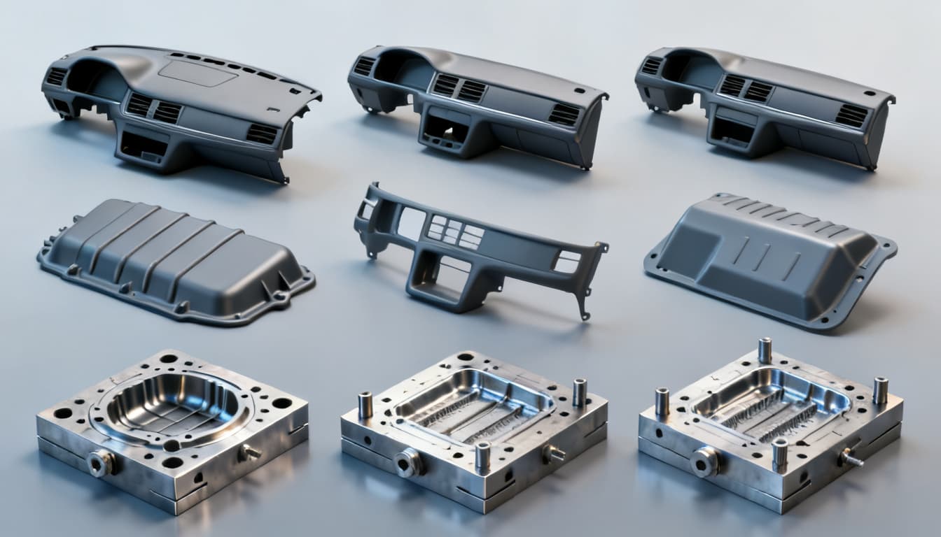
Automotive Injection Molding: 7 Design Tips and Common Mistakes That Compromise Part Strength
A few cents of plastic can halt an entire vehicle program. That’s not hyperbole — it’s exactly what happened when a Tier‑1 supplier substituted standard ABS for the specified glass‑filled nylon in a set of underhood wiring clips. Two months after installation, the clips became brittle, snapped under
Automotive Injection Molding: 7 Design Tips and Common Mistakes That Compromise Part Strength
When a $0.03 Clip Grounds a Production Line: Why Automotive Part Strength Starts at the CAD Stage
A few cents of plastic can halt an entire vehicle program. That’s not hyperbole — it’s exactly what happened when a Tier‑1 supplier substituted standard ABS for the specified glass‑filled nylon in a set of underhood wiring clips. Two months after installation, the clips became brittle, snapped under routine vibration and heat, and triggered a massive recall that rippled through the supply chain. The root cause wasn’t a molding defect; it was a design decision that ignored the thermal and mechanical demands of the engine bay (Ulite case study).
Contrast that failure with a design team that applied a simple radius rule to an interior bracket. By increasing internal corner radii to R = 0.5T — half the nominal wall thickness — they reduced the stress concentration factor from 3.0 to 1.2. The result: a 300% increase in impact strength and a part that sailed through 12G drop tests without a single brittle fracture (LSR checklist). These two stories bookend the reality of automotive injection molding: part strength is determined long before the mold is cut. It lives in the CAD model, in the material selection spreadsheet, and in the DFM review.
For product engineers and injection molding buyers, the lesson is clear. Every wall thickness transition, gate location, and tolerance call‑out either builds robustness into the part or plants the seed for a field failure. This article unpacks the physics, the materials, and the seven design rules that keep automotive components intact on the road — and out of the warranty claim database.
How Melt Flow, Wall Thickness, and Cooling Rates Dictate Part Integrity in Automotive Molding
Injection molding looks simple: melt plastic, push it into a cavity, cool, eject. But the way the melt flows, fills, and solidifies creates a permanent fingerprint of stress inside the part. In automotive applications — where components must survive temperature swings from -40°C to over 120°C, road salt, and constant vibration — that internal stress landscape determines whether a bracket lasts 15 years or 15,000 miles.
Three factors dominate part integrity: melt flow behavior, wall thickness uniformity, and cooling rate symmetry. When molten polymer enters the cavity, it flows along the path of least resistance. Sharp corners, abrupt thickness changes, and poorly placed gates disturb the flow front, creating knit lines — the hidden seams where two flow fronts meet. If that knit line lands at the base of a structural rib, the part’s tensile strength can drop by 20–50% (SyBridge). The same physics governs sink marks: thick sections cool slower than thin ones, pulling material inward and leaving a depression. The fix starts with uniform wall thickness, as the 3ERP defect guide confirms: “To prevent sink marks, ensure uniform wall thickness throughout the part design” (3ERP).
Stress concentration is the silent killer of automotive plastics. Any internal corner sharper than the nominal wall thickness acts as a notch. The LSR checklist quantifies this: an internal radius of R = 0.5T reduces the stress concentration factor from 3.0 to 1.2, effectively tripling impact strength (LSR). For parts that must pass 12G shock tests or survive pothole impacts, this single rule is non‑negotiable.
Cooling rate differentials introduce warpage. Protolabs’ design tips warn that “thin areas will inevitably cool faster than thick ones. That temperature differential can create weak areas, which lead to sink and warp” (Protolabs). In glass‑filled materials, fiber orientation adds another layer of complexity: fibers align with flow, causing anisotropic shrinkage that can twist a long bracket like a potato chip if the gate isn’t placed to balance filling.
The table below captures the typical shrinkage and relative cooling time factors for four workhorse automotive resins. Use it as a starting point when you’re laying out rib patterns and wall sections.
| Resin | Mold Shrinkage (typical, %) | Cooling Time Factor* | Typical Automotive Application |
|---|---|---|---|
| ABS (general purpose) | 0.4 – 0.7 | 1.0 (reference) | Interior trim, bezels, HVAC housings |
| PC/ABS (blend) | 0.5 – 0.7 | 1.1 – 1.2 | Instrument panel carriers, center consoles |
| PA66-GF30 (30% glass‑filled nylon) | 0.2 – 0.5 (flow direction) / 0.5 – 0.9 (transverse) | 1.3 – 1.5 | Underhood brackets, engine covers, structural clips |
| PP-TD20 (20% talc‑filled polypropylene) | 0.8 – 1.2 | 1.0 – 1.1 | Wheel arch liners, battery trays, fan shrouds |
*Cooling time factor relative to an equivalent wall thickness in unfilled ABS; actual values depend on mold temperature and part geometry.
Notice that glass‑filled nylon shrinks differently in the flow and cross‑flow directions. If your mold design doesn’t account for that anisotropy, you’ll chase warpage problems through every sampling run. The takeaway: treat wall thickness, corner radii, and gate placement as a single, interdependent system — not a checklist of isolated features.
Material Showdown: ABS, PC/ABS, and Glass-Filled Nylon for Underhood and Interior Components
Material selection is the most consequential strength decision you’ll make. The Ulite case study is a textbook example: standard ABS clips that worked perfectly in a lab drawer failed catastrophically after two months of underhood heat cycling. The recommended PA66-GF30 would have maintained its mechanical properties at 120°C, but the cost savings of $0.03 per clip looked too good to pass up — until the recall bill arrived (Ulite). Advanced Injection Molding reinforces the point: “Poor design choices often lead to expensive mold modifications, longer lead times, and inconsistent part quality” — and material substitution without engineering validation is one of the most expensive poor choices you can make (Advanced Injection Molding).
The comparison table below puts three automotive staples side by side. Use it to anchor your material discussions with the tooling team before the first steel is cut.
| Comparison Metric | ABS (General Purpose) | PC/ABS (Blend) | PA66-GF30 (30% Glass‑Filled Nylon) | Selection Criteria & Failure Boundary |
|---|---|---|---|---|
| Heat Deflection Temperature (HDT @ 1.8 MPa) | 85 – 95 °C | 105 – 115 °C | 240 – 250 °C | Underhood parts regularly exceed 100 °C; ABS will soften and creep. |
| Notched Izod Impact (23 °C, kJ/m²) | 15 – 25 | 35 – 50 | 10 – 15 (dry‑as‑molded) | PC/ABS excels for interior crash‑relevant parts; PA66-GF30 sacrifices some impact for stiffness. |
| Chemical Resistance | Poor against fuels, oils, and road salts | Moderate; better than ABS but still vulnerable to strong solvents | Excellent resistance to hydrocarbons, glycols, and de‑icing salts | Any fluid contact in the engine bay rules out ABS; PC/ABS needs validation. |
| Relative Material Cost (per kg) | $ (baseline) | $$ (1.3 – 1.6× ABS) | $$$ (1.8 – 2.5× ABS) | Cost premium is justified when the alternative is a field failure and recall. |
| Typical Automotive Use | Interior trim, speaker grilles, glove box doors | Instrument panel substrates, knee bolsters, door panels | Engine covers, intake manifolds, structural brackets, wiring clips | Match the resin to the environment, not just the CAD model. |
Key Takeaway: If your part lives under the hood, start with PA66-GF30 or a comparable heat‑stabilized nylon. The per‑part cost difference is measured in cents; the cost of a brittle fracture on a hot engine is measured in millions. For interior parts that must pass head‑impact and knee‑bolster tests, PC/ABS gives you the ductility ABS lacks. Reserve unfilled ABS for low‑stress, climate‑controlled cabin components where cost pressure is extreme and the thermal envelope never exceeds 80 °C.
7 Design Rules That Keep Automotive Parts From Cracking, Warping, or Sinking on the Road
Automotive programs live and die by PPAP deadlines and zero‑defect targets. The following seven rules are distilled from thousands of mold flow analyses, failure investigations, and tooling revisions. Each rule is paired with the mistake that most often undermines part strength — and the source that backs it up.
| # | Design Rule | Common Mistake That Compromises Strength | Strength Impact & Reference |
|---|---|---|---|
| 1 | Maintain uniform wall thickness throughout the part | Thick bosses and ribs that create sink marks and internal voids | Sink marks act as stress risers and crack initiation sites; uniform walls are the primary defense (3ERP). |
| 2 | Apply generous draft angles — minimum 1° per side, 1.5–3° for textured surfaces | Insufficient draft that causes ejection drag, orange peel, and micro‑cracks | Aerospace panels with 0.5° draft showed orange peel at 10k cycles; automotive A‑surfaces demand more (LSR). |
| 3 | Use internal radii ≥ 0.5T (half the nominal wall) at every corner | Sharp inside corners that concentrate stress 3× higher than a radiused corner | R = 0.5T reduces stress concentration from 3.0 to 1.2, tripling impact strength (LSR). |
| 4 | Position gates so weld lines form in low‑stress zones, not at rib bases | Gating that places knit lines directly in the load path of structural features | Poor gate placement can reduce tensile strength by 22% or more (SyBridge); mold flow simulation is mandatory (3ERP). |
| 5 | Eliminate undercuts or design for side actions and lifters from the start | Adding undercuts without planning mold mechanics, forcing sharp corners or thin steel | Unplanned undercuts lead to weak, flash‑prone parting lines and tool damage (Protolabs DFM). |
| 6 | Specify materials that survive the chemical and thermal environment | Substituting cheaper resin without validating heat and chemical resistance | ABS clips snapped after 2 months underhood; PA66-GF30 prevented the failure (Ulite). |
| 7 | Tolerance only the features that affect function and assembly | Over‑tolerancing every dimension, inflating tooling cost and inspection time | Every unnecessary ±0.01 mm adds machining and inspection expense with zero strength benefit (LSR). |
Let’s unpack a few of these in detail, because the table only hints at the real‑world consequences.
Rule 1 — Uniform Wall Thickness: The most common sink‑mark culprit is a thick boss designed to accept a self‑tapping screw. When the boss wall exceeds 60% of the nominal part wall, the center remains molten long after the surrounding material has solidified. The result is a sink on the opposite surface — and a stress concentration that can initiate a crack during thermal cycling. Core out the boss, use gussets for stiffness, and keep the wall thickness consistent. The 3ERP guide confirms that uniform walls are the primary defense against sink marks, and adjusting holding pressure is a secondary measure (3ERP).
Rule 3 — Internal Radii: The R = 0.5T rule is not a suggestion; it’s a fracture mechanics requirement. The LSR checklist documents that an internal radius equal to half the wall thickness reduces the stress concentration factor from 3.0 to 1.2, enabling parts to pass 12G drop tests without brittle fractures (LSR). For automotive brackets that see repeated shock loads, this is the difference between a part that survives a pothole and one that snaps on the first cold morning.
Rule 4 — Gate Placement: Weld lines are inevitable, but their location is under your control. A knit line at the base of a structural rib acts like a perforation. Both SyBridge and 3ERP emphasize that gate location must be determined by mold flow simulation, not guesswork (SyBridge), (3ERP). If the simulation shows a weld line in a high‑stress area, move the gate, add a flow leader, or adjust the wall thickness to shift the meeting point.
Rule 7 — Tolerancing Discipline: Over‑tolerancing is one of the most expensive design mistakes in injection molding. The LSR checklist puts it bluntly: “Every ±0.01mm of unnecessary injection molding tolerance adds machining time and inspection expense” (LSR). On a four‑cavity automotive connector mold, tightening a non‑functional dimension from ±0.1 mm to ±0.05 mm can double the tooling cost and add weeks to the qualification schedule — with no improvement in part strength or reliability.
Automotive Injection Molding: What Senior Engineers and Buyers Ask Before Tooling Kickoff
In technical reviews and sourcing calls, the same questions surface again and again. Here are the answers that save tooling iterations and keep programs on schedule.
Q: How much draft do I really need for a grained automotive interior panel?
For textured A‑surfaces, a minimum of 1.5° to 3° per side is typical, with deeper grains requiring up to 5°. Insufficient draft causes ejection drag that scuffs the grain, creates orange peel, and accelerates mold wear. The LSR checklist documents aerospace interior panels that showed orange peel at just 10,000 cycles with only 0.5° draft — a failure mode that’s equally relevant to automotive IP skins (LSR). Add an extra degree of draft on the core side of deep ribs to prevent sticking and micro‑cracking during ejection.
Q: What’s the true cost of over‑tolerancing a bracket or housing?
Every unnecessary ±0.01 mm adds machining time, inspection steps, and tooling cost without improving function. The LSR checklist notes that over‑tolerancing is one of the most expensive design mistakes because it inflates piece price and lead time while yielding no performance gain (LSR). For a typical automotive bracket, relaxing a non‑critical datum from ±0.05 mm to ±0.15 mm can reduce mold cost by 10–15% and cut CMM inspection time in half — money better spent on material upgrades or mold flow simulation.
Q: When does glass‑filled nylon (PA66‑GF30) justify its higher material cost over standard ABS?
Whenever the part faces sustained heat above 80 °C, aggressive chemicals, or cyclic loads — typical in underhood clips, brackets, and housings. The Ulite case showed that ABS clips became brittle and snapped in two months, while PA66‑GF30 maintained strength, avoiding a massive recall (Ulite). If your part lives in the engine bay, the material premium is an insurance policy against field failure.
Q: How can I eliminate sink marks on thick bosses without adding cycle time?
Core out the boss to maintain a uniform wall thickness (max 60% of the nominal wall), use generous radii at the base, and optimize holding pressure and time. The 3ERP guide confirms that consistent wall thickness is the primary defense against sink marks, and adding gas‑assist or foaming is a last resort (3ERP). If you must keep the boss solid for thread engagement, consider a localized increase in holding pressure and a longer hold time, but expect a cycle time penalty.
Q: Which DFM checks catch gate‑related weld lines that weaken structural ribs?
Mold flow simulation should map the knit line location; the gate must be positioned so the weld line forms in a low‑stress area, not at the base of a rib. Both SyBridge and 3ERP emphasize that poor gate placement is a leading cause of brittle fracture in automotive structural parts (SyBridge), (3ERP). Before cutting steel, run a fill analysis with the actual gate location and verify that weld lines fall in cosmetic or non‑load‑bearing regions.
Q: What are the early warning signs that a mold design will cause warpage in long glass‑filled parts?
Asymmetric cooling, unbalanced filling, and sharp transitions in wall thickness are red flags. Protolabs’ design tips note that differential cooling between thick and thin sections creates residual stress that warps parts; for glass‑filled materials, fiber orientation must also be managed via gate location to avoid anisotropic shrinkage (Protolabs). If your mold flow simulation shows a temperature difference of more than 10 °C between cavity halves at ejection, or a fill imbalance exceeding 5%, you’re likely to see warpage in the first samples. Adjust cooling line layout and gate position before the mold is built.
Automotive injection molding rewards design discipline. The seven rules above — uniform walls, generous draft, radiused corners, strategic gating, undercut planning, material honesty, and tolerancing restraint — are not theoretical ideals. They are the difference between a part that survives 150,000 miles of thermal cycling, vibration, and road salt, and one that cracks on the first cold start. When you sit down for the next tooling kickoff, bring this list, the material comparison table, and a mold flow simulation that maps every weld line. Your production line — and your warranty reserve — will thank you.
Ready to discuss your next automotive molding project? Get a quote from PandaMolding’s engineering team and put these design rules into practice before the first steel is cut.
References & Further Reading
- Checklist: Common Injection Molding Design Mistakes To Avoid — LSR
- 22 Injection Molding Defects and Mistakes: Causes & Solutions — 3ERP
- 7 Common Injection Molding Defects and How to Avoid Them — SyBridge Technologies
- Why Your Injection Molding Project Failed: Lessons Learned from Real Cases — Ulite
- 9 Mistakes to Avoid When Designing Injection Molded Parts — Protolabs
- Common Injection Molding Design Mistakes to Avoid — Advanced Injection Molding
- DFM Guidelines for Injection Molding — Protolabs
- Injection Molding Design Guide — Xometry