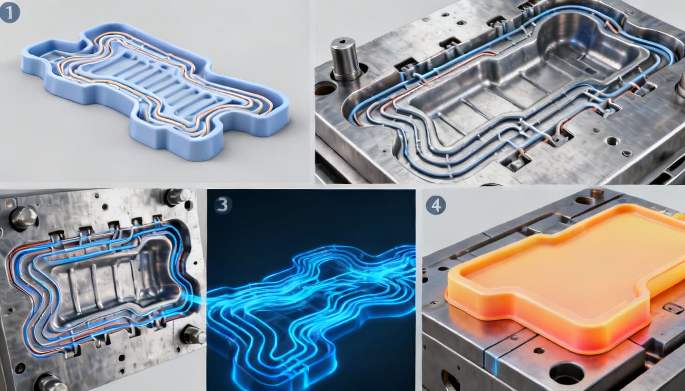
Conformal Cooling Channel Design: A Step-by-Step Guide to Uniform Temperature Distribution
Cycle time still dictates profitability in injection molding, and cooling typically consumes 60–70% of that cycle. For decades, mold makers relied on straight drilled channels—fast to machine but blind to the part’s actual geometry. When walls vary in thickness or the core contains deep ribs, those
Why Conformal Cooling Is No Longer a Luxury in Injection Molding
Cycle time still dictates profitability in injection molding, and cooling typically consumes 60–70% of that cycle. For decades, mold makers relied on straight drilled channels—fast to machine but blind to the part’s actual geometry. When walls vary in thickness or the core contains deep ribs, those straight lines leave hot spots that extend cooling time and drive differential shrinkage. The result is warpage, sink marks, and a process window that shrinks with every new, lighter-weight design.
Product engineers now routinely push for thinner walls and more complex contours to reduce material usage and part mass. Those same features make uniform cooling impossible with conventional drilling. Polyshot’s conformal cooling guide frames the shift clearly: conformal channels “ensure uniform temperature distribution, reduced cycle times, and fewer defects by utilizing precisely engineered cooling channels that conform to the mold’s geometry.” This is no longer an experimental technique. As noted in the ScienceDirect overview, “the production of tools containing complex cooling channels (conformal cooling) is already state of the art and allows the reduction of cycle time and the improvement of the part quality.”
What changed? Additive manufacturing (AM) of mold inserts—primarily laser powder bed fusion (LPBF)—has matured to the point where conformal channels can be printed in maraging steel or stainless steel with reliable mechanical properties. The cost premium for a conformally cooled insert is now measured against the hard savings from a 20–40% shorter cycle and the soft savings from fewer rejected parts. For any program running engineering resins in multi-cavity tools, the question is no longer if conformal cooling should be evaluated, but how to design it correctly the first time.
How Conformal Channels Actually Even Out Mold Temperatures
Cooling a mold is fundamentally a conduction problem. Heat from the molten polymer must travel through the tool steel to the coolant. The rate of heat removal at any point on the cavity surface is inversely proportional to the distance between that point and the nearest cooling channel. When channels are straight and the part is not, that distance varies dramatically—2 mm at one location, 15 mm at another. The result is a temperature map with peaks and valleys that directly imprint on the part as uneven shrinkage.
Conformal channels solve this by maintaining a nearly constant offset from the cavity surface. The MDPI design study states the rule plainly: “To achieve a consistent temperature distribution, it is essential to align the cooling channels with the surface of the mold cavity.” When the channel follows the contour, every point on the cavity sees the same thermal resistance. The coolant path length also becomes more uniform, so the temperature rise of the coolant itself is balanced across the circuit.
The impact is measurable. A PMC-published experimental study compared a straight-drilled mold with a conformal design for a plate-and-wave profile. The straight-channel mold surface reached a maximum of approximately 34°C with noticeable hot spots. The conformal mold surface stayed around 31°C, and no point exceeded 34°C. The temperature distribution tightened from a range of several degrees to a band of just 2–3°C. That uniformity translates directly into less warpage and a shorter time to reach safe ejection temperature.
The table below captures the key design parameters that shift when moving from conventional to conformal channels.
| Parameter | Conventional Straight Channel | Conformal Cooling Channel | Impact on Temperature Uniformity |
|---|---|---|---|
| Distance from cavity surface | Variable, often 2–3× channel diameter; can exceed 15 mm in deep ribs | Constant 1–1.5× diameter (typically 2–6 mm) | Uniform distance eliminates hot spots; reduces max surface temperature by 3–5°C |
| Channel diameter | 8–12 mm (limited by drill size and mold strength) | 4–8 mm (smaller diameters possible with AM) | Smaller channels can follow complex contours more closely |
| Pitch (center-to-center spacing) | Constrained by drill entry; often 2–3× diameter | Optimized via simulation; typically 2–4× diameter | Closer pitch improves heat removal uniformity |
| Reynolds number (turbulence) | Target >4,000; achievable with standard flow rates | Target >4,000; may require higher velocity due to smaller diameter | Turbulent flow ensures high heat transfer coefficient; laminar flow causes uneven cooling |
| Coolant pressure drop | Low (0.5–2 bar) due to smooth drilled walls | Higher (2–5 bar) due to surface roughness (Ra 8–15 µm) and longer path | Must be accounted for in pump sizing; excessive drop reduces flow rate |
| Typical mold surface temperature range | 30–45°C with hot spots up to 50°C (PMC study) | 28–34°C with max deviation <3°C (PMC study) | Narrower range reduces differential shrinkage and warpage |
Key takeaway: The design freedom of conformal channels lets you set the thermal resistance exactly where you need it. But that freedom demands simulation. You cannot guess the right offset or pitch; you must run a coupled flow-thermal analysis to verify that the Reynolds number stays above 4,000 in every branch and that the pressure drop does not exceed your temperature control unit’s capacity.
Conventional vs. Conformal Cooling: When the Straight Line Fails
Straight drilled channels work well for flat or gently curved parts with uniform wall thickness. The moment a part introduces a non-constant thickness—a screw cap with a thick tamper-evident band, a housing with deep bosses, a lens with a thick rim—the straight line fails. A thermal comparison published on ResearchGate examined exactly this scenario for a non-constant-thickness screw cap. The conformal design dramatically reduced both cooling time and temperature variation compared to the conventional layout, confirming that conformal channels are not just a convenience but a necessity for dimensionally stable parts with uneven mass distribution.
Not all conformal patterns are equal. The three most common architectures—spiral, zigzag, and lattice (triply periodic minimal surface, or TPMS)—each bring a different balance of thermal performance, manufacturability, and pressure drop. A recent ScienceDirect review notes that “a more uniform temperature distribution is achieved with spiral type CCCs than the zigzag one,” a finding that aligns with the physics: spiral channels maintain a consistent curvature and offset, while zigzag patterns introduce corners where coolant velocity drops and heat transfer suffers.
| Metric | Straight Drilled | Spiral Conformal | Zigzag Conformal | Lattice (TPMS) Conformal | Selection Criteria |
|---|---|---|---|---|---|
| Cycle time reduction vs. straight baseline | — | 20–40% | 15–30% | 30–50% | Spiral for axisymmetric parts; lattice for maximum heat transfer in complex volumes |
| Temperature uniformity (max ΔT across cavity) | 10–20°C | 2–5°C | 5–10°C | 1–4°C | Spiral and lattice best for tight tolerances; zigzag acceptable for less critical parts |
| Design complexity | Low | Moderate | Low–moderate | High | Zigzag easiest to design manually; lattice requires generative design tools |
| AM manufacturability | Not applicable | Good (LPBF, no support needed if self-supporting) | Excellent (simple toolpath, minimal supports) | Challenging (requires powder removal from fine cells) | Match pattern to AM process capability; zigzag is most forgiving |
| Coolant pressure drop | Low | Moderate | Moderate–high | High (due to tortuous path) | Ensure pump capacity; lattice may need higher pressure or parallel circuits |
| Best application | Simple prismatic parts | Cylindrical cores, bottles, caps | Flat or slightly curved surfaces | Highly complex 3D geometries, conformal cooling of entire insert | Choose based on part symmetry and thermal load distribution |
The screw cap study exemplifies the decision logic: a cylindrical part with a thick band benefits most from a spiral channel wrapped around the core. A flat electronic housing with multiple standoffs might use a zigzag network on the cavity side and a lattice structure inside the core to pull heat from every boss. The pattern must match the thermal symmetry of the part, not the other way around.
A Practical Design Sequence for First-Time Conformal Cooling Projects
Moving from a straight-drilled mold to a conformal design is not a simple CAD swap. It requires a deliberate sequence that starts with part analysis and ends with a validated, printed insert. The following steps draw on the experimental methodology of the PMC study and the design algorithm described in the ScienceDirect review, which controls channel proximity to achieve uniform temperature.
- Map the thermal load. Run a preliminary filling and cooling simulation with a conventional straight-channel layout. Identify hot spots where the cavity surface temperature exceeds the target by more than 5°C. These are your priority zones for conformal routing.
- Define the target temperature window. Based on the resin’s recommended mold temperature and ejection temperature, set a maximum allowable ΔT across the cavity surface. For semi-crystalline engineering resins, a ΔT under 5°C is a good starting point.
- Set the offset rule. Establish a constant distance from the cavity surface to the channel centerline—typically 1.5–2.0 times the channel diameter, with a minimum steel wall of 2 mm after finish machining. This rule becomes the backbone of your channel routing.
- Route the channels. Begin with the hottest zones and work outward. Use spiral paths for cylindrical features, zigzag or serpentine for planar areas, and lattice structures only where the geometry precludes simpler patterns. Avoid dead zones where coolant velocity drops below 1 m/s.
- Select channel cross-sections. Circular channels are the default and easiest to print without supports. D-shaped or elliptical channels can increase the wetted surface area but may require support structures that complicate powder removal. Confirm printability with your AM supplier before committing.
- Simulate the conformal design. Run a coupled flow-thermal simulation (Moldflow, Moldex3D, or ANSYS) with the conformal layout. Compare the cavity surface temperature range, ejection temperature uniformity, and coolant pressure drop against the conventional baseline. Iterate until the ΔT target is met and the pressure drop stays within your TCU’s capability.
- Validate structural integrity. Perform a static FEA with injection pressure applied to the cavity. Check that the minimum wall thickness between channel and cavity does not yield. This step is non-negotiable; a cracked insert erases all cycle-time gains.
- Finalize for AM. Export the insert geometry and review it with the AM supplier. Define minimum feature size, self-supporting angles (≥45° from horizontal), and powder removal ports. Agree on post-processing: heat treatment, machining of parting lines and ejector holes, and surface finishing of the cavity.
The table below consolidates the design rules that should govern every conformal cooling project.
| Design Parameter | Recommended Value | Notes |
|---|---|---|
| Channel distance from cavity surface | 1.5–2.0 × channel diameter (min. 2 mm for mold strength) | Closer improves cooling but risks structural failure; use FEA to verify |
| Channel diameter | 4–8 mm for most inserts; up to 12 mm for large molds | Smaller diameters follow contours better but increase pressure drop |
| Channel cross-section shape | Circular (standard); D-shape or elliptical for higher surface area | Non-circular shapes may require supports; consult AM supplier |
| Minimum wall thickness between channel and cavity | 2–3 mm for tool steel (e.g., 1.2709) after machining | Include machining allowance; thinner walls risk cracking under injection pressure |
| Coolant flow velocity | 2–5 m/s to achieve turbulent flow (Re > 4,000) | Higher velocity improves heat transfer but increases pressure drop |
| Surface roughness (Ra) of printed channels | As-printed: 8–15 µm; can be improved by abrasive flow machining | Roughness increases pressure drop; specify if polishing is needed |
| Support structure removal | Design channels with self-supporting angles (>45° from horizontal) | Avoid trapped powder; use teardrop or oval shapes if necessary |
| Leak tightness test pressure | 1.5× maximum operating pressure, typically 10–15 bar | Conduct before final machining; CT scan for internal defects |
Tip: Involve your AM supplier during step 4, not step 8. A quick design review early in the process can prevent a week of rework when a channel proves unprintable.
Conformal Cooling Questions Engineers Ask Before Cutting Steel
Q: At what production volume does conformal cooling become cost-justified?
The break-even depends on cycle time savings and part value. For high-cavitation molds running engineering resins (PEEK, PPS, glass-filled nylon), even a 15–20% cycle reduction can pay for the added tooling cost within the first year of production. Low-volume commodity parts rarely justify the investment on cycle time alone, but if warpage or sink marks are driving a high reject rate, conformal cooling can be the cheaper path to a capable process—even at 50,000 shots per year.
Q: How do I validate that a conformal design will actually improve temperature uniformity before cutting metal?
Run a coupled flow-thermal simulation (Moldflow, Moldex3D, or ANSYS) with both conventional and conformal layouts. Compare the cavity surface temperature range and ejection temperature uniformity. The PMC study’s methodology—using thermocouple arrays on a test mold—provides a physical validation template for critical programs. If the part carries high liability or tight tolerances, build a single-cavity test insert and map temperatures under production conditions before committing to a multi-cavity tool.
Q: Spiral, zigzag, or lattice: which conformal pattern should I choose?
Spiral channels generally deliver the most uniform temperature distribution for axisymmetric parts, as shown in the ScienceDirect review. Zigzag patterns are easier to print and work well on flat or gently curved surfaces but can create local hot spots at the sharp turns. Lattice-based (TPMS) designs offer the highest surface area and can cool complex volumes uniformly, but they demand careful pressure drop analysis and a printer capable of fine feature resolution. Match the pattern to the part’s thermal symmetry and the AM process capability.
Q: What are the biggest pitfalls when moving from a straight-drilled mold to a conformal design?
Common mistakes include ignoring coolant pressure drop (printed channels often have higher surface roughness, which increases flow resistance), neglecting support removal in small channels, and designing channels too close to the cavity surface, which risks mold strength. Always run a structural FEA alongside thermal simulation and involve the AM supplier early to define minimum wall thickness and self-supporting geometries. Another pitfall is assuming that conformal cooling alone fixes a poorly designed part—gate location and wall thickness still matter.
Q: Can conformal cooling channels be added to an existing mold, or does it require a new build?
Retrofitting is possible only if the mold was designed with replaceable inserts. In most cases, conformal cooling is integrated into a new insert set manufactured via laser powder bed fusion or a similar AM process. The PMC article’s experimental setup used a dedicated CCC insert, which is the standard approach. If the existing mold base is in good condition, you can often drop in a conformally cooled insert set without rebuilding the entire tool.
Q: How do I specify and inspect a conformally cooled insert from an additive manufacturing vendor?
Define the required channel diameter tolerance, surface roughness (Ra), and leak-tightness. Request CT scans of the first article to verify channel continuity and wall thickness. Include a pressure test at 1.5× operating pressure. The Polyshot guide emphasizes that post-processing—heat treatment, machining of mating surfaces—must preserve channel integrity. Specify that no abrasive blasting or machining operations may block or deform the channels, and require a final flow test with water at the design flow rate to confirm pressure drop matches simulation predictions.
References & Further Reading
- Conformal Cooling Guide: Everything You Need to Know in 2024 – Polyshot
- Conformal Cooling Channel – an overview | ScienceDirect Topics
- Conformal Cooling Channel Design for Improving Temperature Distribution on the Cavity Surface in the Injection Molding Process – PMC
- Design and Optimization of Conformal Cooling Channels for Increasing Cooling Efficiency in Injection Molding – MDPI
- Thermal Comparison of Conventional and Conformal Cooling Channel Designs for a Non-Constant Thickness Screw Cap – ResearchGate
- Recent advancement in conformal cooling channels: A review on design, simulation and future trends – ScienceDirect
- Conformal Cooling Services – PandaMolding
Conformal cooling channel design is no longer an exotic option—it is a practical engineering tool that pays for itself in cycle time, part quality, and process stability. The step-by-step approach outlined here, grounded in published research and field experience, gives you a repeatable path from hot spot identification to a validated, printed insert. When you are ready to apply conformal cooling to your next mold, get in touch with our team to discuss your project requirements and receive a detailed quotation.