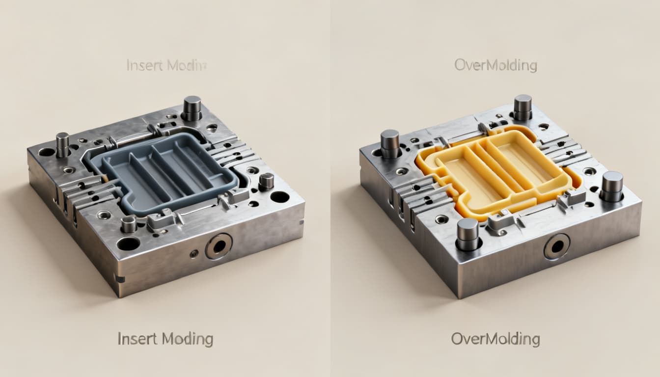
Insert Molding vs. Overmolding: Avoid These 5 Common Design Pitfalls
Multi-material assemblies are no longer a niche luxury — they’re a competitive requirement in medical devices, automotive interiors, consumer electronics, and industrial housings. Industry analysis from Plastics Technology consistently tracks double‑digit growth in multi‑shot and insert molding appl
Why Insert Molding and Overmolding Decisions Go Wrong Before the First Shot
Multi-material assemblies are no longer a niche luxury — they’re a competitive requirement in medical devices, automotive interiors, consumer electronics, and industrial housings. Industry analysis from Plastics Technology consistently tracks double‑digit growth in multi‑shot and insert molding applications, driven by lightweighting, miniaturization, and the need to combine rigid, flexible, and conductive functions in a single part. Yet behind the glossy product launches, a quieter pattern repeats: designs that looked flawless on the screen fail during first‑article trials or, worse, generate field returns six months into production.
At Panda Molding, our application engineers routinely review RFQs where the fundamental choice between insert molding and overmolding was made without a thorough understanding of process limits. We see parts with threaded inserts that spin freely under torque, overmolded seals that delaminate after thermal cycling, and tooling budgets that explode because a design assumed a simple two‑shot mold when a well‑designed insert molding cell would have delivered the same function at half the upfront cost. These aren’t material defects — they’re design‑phase decisions that ignored the mechanical, thermal, and logistical realities of each process.
This article walks you through the core differences between insert molding and overmolding, then zeroes in on the five design pitfalls that most often derail projects. You’ll leave with actionable guidelines, a decision matrix you can apply to your next part, and answers to the questions our own customers ask before committing to tooling.
The Core Mechanics That Separate Insert Molding from Overmolding
Before you can avoid mistakes, you need a clear mental model of what each process actually does. The names sound similar, and both produce a single integrated component, but the sequence of events, the bond mechanism, and the tooling architecture are fundamentally different.
Insert molding places a pre‑fabricated component — typically a metal bushing, threaded insert, pin, or ceramic insulator — into the mold cavity before the plastic melt is injected. The molten resin flows around the insert, encapsulating it. When the part cools, the plastic shrinks onto the insert, creating a mechanical grip. Any additional adhesion relies on the geometry of the insert (knurling, undercuts, through‑holes) or, less commonly, on a chemical primer applied before molding. The insert can be hand‑loaded, robotically placed, or fed from a magazine, but it is always a discrete, solid object that was manufactured in a separate operation.
Overmolding, by contrast, starts with a molded substrate — often a rigid thermoplastic — and then injects a second material (a softer elastomer, a different color, or even a second rigid resin) onto or around that substrate in a subsequent shot. The bond between the two materials can be mechanical (interlocking features molded into the first shot), chemical (compatible polymer chains that fuse during the second injection), or a combination of both. True two‑shot overmolding uses a single machine with multiple injection units and a rotating or indexing mold, while “pick‑and‑place” overmolding transfers the substrate from one machine to another.
The table below distills the key technical differences that influence design decisions.
| Parameter | Insert Molding | Overmolding (Two‑Shot) | What It Means for Your Design |
|---|---|---|---|
| Process sequence | Insert placed → single resin shot | Substrate molded → second material shot | Insert molding adds a pre‑molding step; overmolding requires a substrate that can survive a second heat cycle. |
| Typical cycle time | 20–45 s (manual loading); 15–30 s (automated) | 30–70 s (two‑shot rotary); 45–90 s (transfer) | Insert molding can be faster for simple geometries; overmolding cycle is dominated by cooling of the thicker substrate. |
| Tooling complexity | Single‑cavity tool with insert retention features; simpler mold base | Two injection units + rotating platen or indexing mold; precise alignment required | Insert molding tooling is 30–50% less expensive and 2–4 weeks faster to build. |
| Bond mechanism | Primarily mechanical (shrink fit, knurling, undercuts); chemical adhesion is secondary | Mechanical interlocks + chemical fusion between compatible materials | Insert molding demands robust mechanical interlock design; overmolding can achieve hermetic seals with material pair selection. |
| Material compatibility | Insert material can be metal, ceramic, or high‑temp polymer; resin choice is independent | Substrate and overmold resins must be chemically compatible or designed with interlocks; melt temperature mismatch must be managed | Insert molding offers wider material freedom; overmolding requires careful pairing (e.g., TPE over PP, LSR over PA with primer). |
| Part geometry flexibility | Inserts are typically localized; not suited for full‑surface coverage | Can cover entire surfaces, create soft‑touch grips, seals, or multi‑color aesthetics | Choose overmolding when you need a continuous elastomeric skin; insert molding when you need discrete functional elements. |
| Typical applications | Threaded bosses, electrical connectors, sensor housings, surgical instrument handles | Power tool grips, gasketed enclosures, wearable device bands, automotive interior trim | Align process with the primary function: mechanical fastening vs. ergonomic or sealing surface. |
These differences are not academic — they directly affect the design rules you must follow. Plastics Technology’s processing guides emphasize that insert molding success hinges on insert placement accuracy and melt flow around the insert, while overmolding demands precise control of the substrate temperature at the moment of the second shot. Panda Molding’s production floor routinely runs both processes, and we’ve learned that the most costly mistakes happen when a designer treats an overmolded part like an insert‑molded one, or vice versa.
Side-by-Side: When to Choose Insert Molding Over Overmolding (and Vice Versa)
Choosing the right process isn’t just about what’s technically possible — it’s about matching the manufacturing method to your production volume, cost targets, and functional requirements. The decision matrix below captures the factors our engineering team at Panda Molding walks through with every customer during the DFM phase.
| Decision Factor | Insert Molding | Overmolding (Two‑Shot) | Selection Guidance |
|---|---|---|---|
| Production volume | Best for low‑to‑medium volumes (1k–50k/year) or high‑mix environments | Excels at high volumes (>50k/year) where automation amortizes tooling cost | At 10k parts, insert molding usually wins on total cost; at 100k, two‑shot overmolding often yields a lower unit price. |
| Insert complexity | Handles complex metal shapes (threaded, splined, overmolded magnets) with ease | Inserts are typically the first‑shot substrate; adding a third material is possible but costly | If your design needs a precision metal thread, insert molding is the direct path. |
| Bond strength requirement | Mechanical retention; pull‑out forces of 50–500 N depending on insert design | Chemical bond can exceed substrate strength; peel strengths >5 N/mm achievable | For hermetic seals or high peel resistance, overmolding with compatible materials is superior. |
| Material pair flexibility | Almost any plastic can encapsulate almost any rigid insert | Limited to material pairs that bond or can be mechanically locked; common pairs: TPE/PP, TPU/PC, LSR/PA | If you need a soft‑touch grip on a polycarbonate housing, overmolding is the standard solution. |
| Upfront tooling cost | $5,000–$20,000 for a single‑cavity production tool | $20,000–$80,000+ for a two‑shot rotary tool | Budget‑constrained projects often start with insert molding and transition to overmolding as volumes grow. |
| Per‑part cost at scale | Higher labor cost if inserts are hand‑loaded; automated cells reduce this | Lower labor; cycle time is the main cost driver | Run a total‑cost‑of‑ownership analysis including labor, scrap, and secondary operations. |
| Design change agility | Easier to modify insert geometry or swap insert material without retooling the entire mold | Changing substrate or overmold material may require re‑validating the bond and modifying both mold halves | If your product family evolves frequently, insert molding offers more flexibility. |
Real‑world scenarios make the choice clearer. A medical device manufacturer needed stainless steel threaded inserts in a handheld diagnostic tool. The annual volume was 15,000 units. Insert molding allowed them to use off‑the‑shelf inserts, a simple mold, and manual loading that kept tooling under $12,000. Two years later, when volumes climbed to 80,000, they migrated to an automated insert‑loading cell that cut per‑part cost by 30% without redesigning the mold.
Conversely, a consumer electronics company developing a waterproof wearable band needed a continuous TPE skin over a rigid nylon frame. Insert molding couldn’t deliver the seamless seal, so they invested in a two‑shot overmolding tool. The higher tooling cost ($55,000) was offset by eliminating a manual gasket‑assembly step, and the IP67 rating was achieved straight from the mold. Plastics Technology has documented similar case studies where overmolding eliminated secondary operations and improved reliability. Panda Molding’s application engineers use this kind of trade‑off analysis to guide customers toward the right process before the first steel is cut.
Five Design Pitfalls That Derail Insert Molding and Overmolding Projects
Even when you’ve selected the right process, small geometry details can cause big problems. The following five pitfalls appear repeatedly in parts that reach our DFM review at Panda Molding. Each one is avoidable if you address it in the CAD model, not on the production floor.
| Pitfall | What Goes Wrong | How to Fix It |
|---|---|---|
| 1. Insufficient mechanical interlock | Inserts with smooth outer diameters or shallow knurling spin or pull out under torque. Plastic shrinkage alone rarely provides enough retention. | Specify knurling (diamond or straight) with a depth of 0.2–0.5 mm, add undercuts, or incorporate through‑holes that allow plastic to form rivet‑like heads. For threaded inserts, ensure the knurl pattern is fully embedded in the plastic, not just at the surface. |
| 2. CTE mismatch causing stress cracks | Metal inserts (CTE ~10–20 ppm/°C) and glass‑filled plastics (CTE ~20–40 ppm/°C) expand at different rates. During cooling or thermal cycling, the plastic can crack around the insert, especially at sharp corners. | Design generous radii (≥0.5 mm) at insert edges. Choose plastics with lower and more isotropic shrinkage. Use mold flow analysis to predict stress concentrations and, if necessary, preheat inserts to 80–120°C to reduce the thermal shock. |
| 3. Poor venting around inserts | Inserts act as flow obstructions. Trapped air or gas burns the resin, causing voids, short shots, or surface defects at the insert‑plastic interface. | Add venting channels (0.02–0.05 mm deep) in the mold steel near the insert pocket. Position the gate so melt flows from the insert outward, pushing air toward the parting line. For complex inserts, consider vacuum‑assisted venting. |
| 4. Material incompatibility in overmolding | Selecting a substrate and overmold that won’t bond chemically, or whose melt temperatures are too far apart, leads to delamination. For example, overmolding TPE onto acetal (POM) without mechanical interlocks almost always fails. | Use proven material pairs: TPE over PP, TPU over PC/ABS, LSR over PA with primer. When in doubt, request bond strength data from the material supplier. Design mechanical interlocks (dovetails, through‑holes) as a backup even when chemical bonding is expected. |
| 5. Insert preheating and positioning errors | Cold inserts cause premature freezing of the melt front, resulting in incomplete encapsulation or knit lines. Misaligned inserts (shifted by injection pressure) create wall thickness variations and functional failures. | Preheat inserts to within 20–30°C of the mold temperature. Use precision locating features (pins, magnets, or vacuum cups) in the mold to hold inserts in place. Validate insert position with a vision system or in‑mold sensors for critical applications. |
Pitfall 1 — Insufficient mechanical interlock: The most common root cause of insert pull‑out is a smooth insert body. Even with high‑shrinkage resins, the clamping force from shrinkage alone is unpredictable. Plastics Technology’s design guidelines consistently recommend a minimum knurl depth of 0.25 mm for inserts under 10 mm diameter. At Panda Molding, we’ve seen a simple change from a straight knurl to a diamond knurl increase pull‑out resistance by 40% without changing the insert material or plastic grade.
Pitfall 2 — CTE mismatch: The problem intensifies when the plastic is glass‑filled, because the filler reduces the resin’s ability to absorb stress. A sharp corner on a brass insert embedded in 30% glass‑filled nylon will almost certainly nucleate a crack after a few thermal cycles from -40°C to 85°C. Adding a radius to the insert edge and selecting a toughened nylon grade can eliminate the failure. Mold flow simulation software can map the residual stress field and guide the insert geometry.
Pitfall 3 — Poor venting: Inserts create dead zones where air cannot escape. The telltale sign is a brownish burn mark or a porous surface at the downstream side of the insert. The fix is often as simple as adding a vent groove along the ejector pin or using a porous metal insert in the mold to allow air to evacuate. Panda Molding’s tooling team routinely incorporates venting channels in insert pockets, a detail that many generic mold makers overlook.
Pitfall 4 — Material incompatibility: Overmolding relies on a heat‑activated bond. If the substrate surface temperature drops below the overmold material’s melting point before the second shot, no chemical bond forms. This is why transfer overmolding (moving the substrate from one machine to another) is riskier than true two‑shot molding. Even with a two‑shot process, choosing a substrate like POM or HDPE without mechanical interlocks is a recipe for peeling. Always consult the material supplier’s overmolding compatibility chart and prototype with the exact grade you’ll use in production.
Pitfall 5 — Insert preheating and positioning: In high‑speed insert molding, the insert often arrives at room temperature. When the melt hits a cold insert, a skin layer solidifies instantly, preventing proper adhesion and creating a weak interface. Preheating the insert to just below the mold temperature can restore flow and improve encapsulation. Positioning is equally critical: injection pressures can reach 500–1000 bar, enough to shift an insert that is merely resting in a pocket. Positive retention — spring‑loaded pins, magnets, or vacuum — is not optional for inserts with tight positional tolerances.
Questions Engineers Ask Before Committing to an Insert or Overmolding Design
Q: How do I determine the minimum wall thickness around a metal insert to avoid sink marks?
A: A rule of thumb is 40–60% of the nominal wall thickness for the plastic around the insert, but it depends on material shrinkage. For example, if your part has a 2.5 mm nominal wall, the plastic between the insert and the outer surface should be at least 1.0–1.5 mm. Use mold flow analysis to verify that the packing pressure can compensate for shrinkage. Panda Molding recommends a minimum of 0.8–1.0 mm for ABS and similar amorphous resins, and slightly more for semi‑crystalline materials like nylon, which exhibit higher shrinkage. Sink marks also depend on insert geometry — a large thermal mass (like a thick brass insert) will cool slower and exacerbate sinking, so consider hollow or reduced‑mass inserts where possible.
Q: Can I overmold liquid silicone rubber (LSR) onto a thermoplastic substrate, and what bonding method works best?
A: Yes, LSR overmolding is possible but requires a primer or plasma treatment for adhesion unless you are using self‑bonding LSR grades specifically formulated for thermoplastics. Mechanical interlock features (undercuts, holes) provide a reliable backup. Process parameters must be tightly controlled: the substrate must be heated to 120–150°C to promote bonding, and the LSR injection speed and pressure must be balanced to avoid flash while filling the cavity. Panda Molding has successfully overmolded LSR onto PA and PBT substrates for medical and automotive seals, and we always validate bond integrity with peel tests per ASTM D903.
Q: What is the typical cost difference between insert molding and two-shot overmolding for volumes of 10,000 vs 100,000 parts?
A: Insert molding usually has lower tooling cost but higher per‑part labor if inserts are hand‑loaded. For 10k parts, insert molding may be cheaper overall because the $10,000–$15,000 tooling cost dominates. At 100k parts, two‑shot overmolding’s automation often yields a lower total cost despite a $40,000–$60,000 tooling investment, because the per‑part labor is nearly zero and cycle times are consistent. The exact crossover point depends on part complexity, insert cost, and local labor rates. Get a detailed quote from Panda Molding to run a total‑cost‑of‑ownership comparison for your specific design.
Q: How do I validate the bond strength in an overmolded part?
A: Perform peel or pull tests per ASTM D903 or D1876, or use a custom fixture to measure separation force. A 90‑degree peel test is common for flexible overmolds on rigid substrates; a lap‑shear or pull‑off test works for rigid‑to‑rigid bonds. Cross‑section analysis can check for voids at the interface. Panda Molding can coordinate testing during first article inspection and provide a bond strength report that includes failure mode (cohesive vs. adhesive) to guide material or process adjustments.
Q: When should I use a mechanical interlock versus chemical bonding in insert molding?
A: Use mechanical interlock (knurling, holes, undercuts) when the insert material does not bond well with the plastic or when thermal cycling is expected. Mechanical retention is predictable and doesn’t degrade with temperature. Chemical bonding (adhesives or primers) can reduce stress concentrations and allow smoother insert surfaces, but it adds process steps and may fail if the adhesive cures improperly or ages. Evaluate based on operating temperature, load, and whether the insert must be electrically insulated from the plastic. In most industrial applications, a robust mechanical interlock is the safer default.
Q: What are the lead time implications for tooling each process?
A: Insert molding tooling is typically simpler and 2–4 weeks faster to build than a two‑shot mold, which requires precise alignment and a rotating or indexing mechanism. A straightforward insert mold can be completed in 4–6 weeks, while a two‑shot overmold tool often takes 8–12 weeks. Complex overmold tools with multiple cavities or unscrewing cores can add 4–8 weeks. Panda Molding provides realistic timelines based on part complexity and can often overlap tooling build with process development to compress the overall schedule.
References & Further Reading
- Plastics Technology — Injection molding industry news, processing guides, and multi‑material molding case studies.
- Panda Molding — Professional injection molding services, including insert molding and overmolding DFM support.
- ASTM D903 — Standard test method for peel or stripping strength of adhesive bonds.
- ASTM D1876 — Standard test method for peel resistance of adhesives (T‑peel test).
- Panda Molding Contact — Request a quote or discuss your insert/overmolding project with an application engineer.
Ready to move your multi‑material design from screen to production? Our team at Panda Molding reviews hundreds of insert and overmolding designs each year, catching the pitfalls described here before they become costly tooling changes. Reach out today for a free DFM assessment and a detailed quote tailored to your volume and performance requirements.