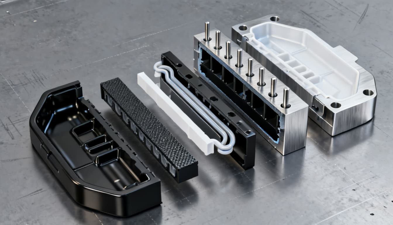
Specifying Critical Tolerances in Custom Injection Molding: An Engineer’s Selection Guide
Every product engineer wants parts that fit perfectly, but the fastest way to blow a tooling budget is to blanket a drawing with tight tolerances on features that don’t need them. Over-specifying tolerances can double mold fabrication costs, stretch lead times by weeks, and drive up piece-part price
Specifying Critical Tolerances in Custom Injection Molding: An Engineer’s Selection Guide
The High Cost of Over-Tolerancing in Custom Injection Molding
Every product engineer wants parts that fit perfectly, but the fastest way to blow a tooling budget is to blanket a drawing with tight tolerances on features that don’t need them. Over-specifying tolerances can double mold fabrication costs, stretch lead times by weeks, and drive up piece-part prices without improving function. The injection molding industry has long understood this tension: as SEAWIN puts it, the selection of injection molding tolerances is essentially an art of balancing functional requirements and cost.
When you call out ±0.02 mm on a cosmetic surface or a non-mating edge, you force the molder into a corner. The mold must be machined to tighter clearances, often requiring slower EDM passes, more frequent electrode changes, and additional polishing steps. In production, the process window narrows dramatically. Molders may need to slow cycle times, increase pack pressure, and perform hourly dimensional checks with SPC alarms—all of which raise the part price. Scrap rates climb because even minor material lot variations can push dimensions out of spec. Jiga notes that a general tolerance of ±0.1 mm on small dimensions is readily achieved, but as the feature becomes more complex or the part envelope grows, holding that band becomes exponentially more expensive.
I’ve seen projects where a single over-toleranced snap-fit added 30% to the mold cost and delayed first-article approval by three weeks. The irony? The snap-fit would have functioned perfectly at ±0.15 mm. The real skill isn’t chasing zero deviation—it’s knowing which dimensions are truly critical to function, assembly, and appearance, and then applying the right tolerance class from recognized standards. That’s where DIN 16901 and ISO 20457 come in.
Decoding DIN 16901 and ISO 20457: What Tolerance Classes Actually Mean for Your Part
For decades, DIN 16901 served as the primary reference for injection molding tolerances. Today, ISO 20457 has largely superseded it, but the core framework remains: a series of tolerance classes, designated DCTG 1 through DCTG 8, that define permissible dimensional variation based on part size, material, and feature type. Understanding these classes lets you communicate precision requirements in a language that molders and quality engineers already speak.
Boyan Manufacturing explains that high-precision tolerances range from DCTG 1 to DCTG 3 for critical components, while EzraMade notes that standard precision falls under DCTG 4 to DCTG 8. In practice, DCTG 1–3 are reserved for bearing seats, optical alignment features, and precision snap-fits. DCTG 4–6 cover most commercial and industrial parts, and DCTG 7–8 apply to non-functional, large, or highly flexible components where generous variation is acceptable.
The table below translates these classes into typical achievable tolerances for small to medium features (under 50 mm) in a well-designed mold with a stable process. Actual values shift with material and geometry, but this gives you a starting point for specification.
| Tolerance Class | Typical Application | Achievable Tolerance (mm) for Features <50 mm | Notes |
|---|---|---|---|
| DCTG 1 | Precision bearing seats, optical interfaces | ±0.02 – ±0.05 | Requires high-precision mold, stable material, and tight process control. Often needs CMM verification. |
| DCTG 2 | Critical snap-fits, gear centers | ±0.03 – ±0.06 | Demands optimized gate location and packing profile. SPC monitoring recommended. |
| DCTG 3 | Functional mating surfaces, seals | ±0.05 – ±0.08 | Common for many engineering components. Achievable with scientific molding. |
| DCTG 4–5 | General commercial parts, enclosures | ±0.08 – ±0.15 | Standard precision for most injection molded parts. Good balance of cost and quality. |
| DCTG 6–8 | Large panels, non-functional covers, flexible parts | ±0.15 – ±0.50+ | Wider bands accommodate shrinkage variation and warpage. Suitable for cosmetic or low-stress applications. |
These ranges align with the baseline guidance from Super-Ingenuity, which states that injection molding typically holds ±0.05–±0.15 mm on mold-fixed CTQ features for small/medium parts. The key takeaway: DCTG 1–3 is not a default. Reserve it for the handful of dimensions that truly control product performance, and let the rest of the part breathe. This approach alone can cut tooling costs by 15–25% and reduce quality disputes during production.
Material Matters: How Resin Choice Shrinks or Expands Your Tolerance Window
You can’t separate tolerance capability from material behavior. Every resin shrinks as it cools in the mold, and that shrinkage varies with wall thickness, flow direction, and filler content. A tolerance that’s easy to hold in glass-filled nylon may be nearly impossible in unfilled polypropylene. Protolabs emphasizes that part design, material selection, and tool design must be considered together to achieve preferred tolerances, and their scientific molding approach optimizes fill, pack, and hold to minimize variation. FirstMold adds that complex features like deep pockets or thin walls can be difficult to mold to tight tolerances, and that draft and mold design play a huge role in final precision.
The table below compares four common resin families and their typical tolerance bands for small features. Use it as a reality check before you commit to a material and a tolerance class.
| Material | Typical Shrinkage (%) | Achievable Tolerance Band (mm) for Features <50 mm | Selection Notes |
|---|---|---|---|
| Unfilled ABS | 0.4 – 0.7 | ±0.05 – ±0.10 | Good dimensional stability; easy to mold. Excellent for enclosures and consumer products. Warpage is low if wall thickness is uniform. |
| Polycarbonate (PC) | 0.5 – 0.7 | ±0.05 – ±0.10 | Higher melt viscosity requires careful venting and packing. Transparent grades demand strict process control to avoid sinks and voids. |
| Glass-Filled Nylon (PA66 GF30) | 0.2 – 0.5 (flow direction dependent) | ±0.03 – ±0.08 | Low and predictable shrinkage enables tight tolerances, but anisotropic shrinkage can cause warpage. Use mold flow analysis to optimize gate location. |
| Unfilled POM (Acetal) | 1.8 – 2.5 | ±0.10 – ±0.20 | High shrinkage demands wider tolerances. Excellent for gears and bearings if designed with uniform walls and generous radii. |
| Polypropylene (PP) | 1.5 – 2.5 | ±0.15 – ±0.30 | Very forgiving for living hinges and flexible parts, but tight tolerances are costly. Expect significant post-mold dimensional change. |
Notice how glass-filled nylon can hold tighter tolerances than unfilled ABS, but only if you manage warpage. That’s where scientific molding and mold flow simulation become non-negotiable. Protolabs’ fill-pack-hold optimization is a perfect example: by precisely controlling how the cavity is packed and held, you can reduce variation across dozens of runs. When you’re pushing for DCTG 2 on a glass-filled part, invest in upfront simulation and plan for a slightly longer mold qualification phase. The payoff is a process that delivers consistent parts from the first shot to the hundredth run.
From Drawing to Mold: A 5-Point Checklist for Specifying Tolerances That Molders Can Actually Hold
Over the years, I’ve distilled the tolerance specification process into five actionable steps. These aren’t theoretical—they’re the same checklist I walk through with our engineers at PandaMolding before we cut steel.
- Identify and isolate CTQ features. Circle the dimensions that directly affect fit, function, or safety. Everything else gets a commercial tolerance. If you can’t explain why a dimension is critical, it probably isn’t.
- Engage your molder during design, not after. A 30-minute DFM review can reveal that a tight bore tolerance is impossible because of the parting line location, or that a simple gate move can cut warpage in half. SEAWIN highlights that real-time SPC monitoring and early collaboration are key to holding agreed-upon standards.
- Apply GD&T with datums that reflect the molding process. Use datums on the mold-fixed side (A-side) where possible. Avoid datuming on surfaces formed by moving slides or lifters unless you’ve accounted for their inherent variation. Profile tolerances often make more sense than linear ± dimensions for complex contours.
- Design in draft and uniform wall thickness from day one. FirstMold warns that inadequate draft leads to parts sticking and dimension variation. A minimum of 0.5° on untextured surfaces and 1–2° on textured ones prevents ejection-induced distortion. Consistent wall thickness minimizes differential shrinkage that throws off flatness and hole positions.
- Define the inspection method and reporting requirements upfront. Will you accept CMM dimensional reports, or do you need full PPAP Level 3 with SPC data? Super-Ingenuity notes that for automotive programs, PPAP is standard, and comprehensive inspection reports ensure tolerances meet agreed-upon standards. Specifying this early avoids disputes when parts arrive.
Even with a solid checklist, certain pitfalls trip up engineers repeatedly. The table below captures the most common ones and how to avoid them.
| Pitfall | Consequence | Solution |
|---|---|---|
| Over-tolerancing non-functional cosmetic surfaces | Unnecessary tooling cost, higher scrap, slower cycles | Apply DCTG 6–8 or general profile tolerances; let the molder use standard machining practices. |
| Ignoring draft and ejection forces | Part distortion, drag marks, inconsistent dimensions | Add draft per material supplier guidelines; simulate ejection in mold flow. |
| Not accounting for material shrinkage anisotropy | Out-of-spec dimensions in one direction even though the other is fine | Use mold flow analysis to predict differential shrinkage; adjust gate location or add ribs. |
| Using ambiguous datums (e.g., center of a flexible feature) | Measurement disputes and rejected lots | Choose rigid, mold-fixed datums; define datum targets clearly on the drawing. |
| Skipping process capability studies before production | Chronic borderline dimensions and high inspection costs | Require a capability study (Cpk ≥ 1.33) on CTQ dimensions during mold qualification. |
When you follow this checklist and watch for these pitfalls, you transform tolerance specification from a guessing game into a repeatable engineering decision. The molder gets a clear target, and you get parts that assemble without rework.
Critical Tolerance Questions Engineers Ask Before Cutting Steel
Q: What’s the tightest tolerance I can realistically hold in injection molding?
A: For small features with high-precision tooling and rigorous process control, ±0.05 mm is a realistic floor. In some cases, mold-fixed CTQ features on small/medium parts can reach ±0.05–±0.15 mm, as noted by Super-Ingenuity. Pushing below ±0.02 mm is possible only with exceptional materials, mold temperature control, and in-process gauging—and it comes with a steep cost premium.
Q: When should I specify DCTG 1–3 instead of DCTG 4–8?
A: Reserve DCTG 1–3 for critical functional interfaces—bearing seats, precision snap-fits, gear tooth profiles, or optical alignment features. For most commercial parts, DCTG 4–8 is sufficient and far more economical. Boyan Manufacturing reinforces that high-precision classes are intended for components where failure would compromise safety or core function.
Q: How do I account for post-molding warpage in my tolerance stack?
A: Start with mold flow analysis to predict warpage magnitude and direction. Then widen tolerances on non-critical areas or specify post-molding fixturing to hold shape during cooling. Protolabs uses scientific molding to optimize fill, pack, and hold, which minimizes residual stress and warpage. For large flat parts, consider adding ribs or changing gate locations to balance flow.
Q: Can I hold ±0.05 mm on a 200 mm part?
A: It’s extremely challenging. As part size increases, shrinkage variation accumulates, and even a 0.1% difference in shrinkage across 200 mm translates to 0.2 mm of variation. Expect ±0.15 mm or more for large envelopes. Jiga confirms that large envelopes and flatness-critical surfaces need wider bands. If you must hold tight tolerances over a long span, consider breaking the part into smaller assembled components or using in-mold sensors for closed-loop control.
Q: What’s the cost premium for high-precision tolerances?
A: High-precision molds can cost 20–50% more than standard molds due to tighter machining, more frequent inspection, and the need for higher-grade tool steels. In production, you’ll face higher scrap rates and more frequent quality checks. SEAWIN frames it as an art of balancing functional requirements and cost—a premium that only makes sense when the part’s performance absolutely demands it.
Q: How do I verify tolerances in production?
A: Request CMM dimensional reports and SPC data for CTQ features. For automotive or high-reliability applications, PPAP Level 3 is the standard. SEAWIN implements real-time SPC monitoring with automatic alarms, and provides comprehensive inspection reports. Super-Ingenuity also emphasizes that final acceptance must define inspection methods upfront. Agree on sampling frequency and reporting format before production begins.
References & Further Reading
- Injection Molding Tolerances: Balance Precision & Cost – SEAWIN INDUSTRIAL LIMITED
- A Guide to Injection Molding Tolerances – Jiga
- Understanding Injection Molding Tolerances – Protolabs
- Understanding Injection Molding Tolerances: An Essential Guide – FirstMold
- Injection Molding Tolerances: DIN 16901, ISO 20457, and Our Practical Guidelines – Boyan Manufacturing Solutions
- Injection Molding Tolerance Standards: ISO 20457, DIN 16742, SPI Finish & Automotive PPAP – Super-Ingenuity
- Injection Molding Tolerances – EzraMade
Smart tolerance specification is one of the highest-leverage skills an injection molding buyer or product engineer can develop. It directly controls tooling cost, part price, and production risk. By applying the right standard class, matching it to your material, and collaborating early with an experienced molder, you can hit functional targets without overpaying. If you’re ready to discuss your next project or need a DFM review on a challenging part, get a quote from our team at PandaMolding—we’ll help you translate your design into a moldable, cost-effective reality.