Aerospace Interior Component Injection Molding
Precision-engineered Aerospace Interior Component Injection Molding from Panda Molding delivers lightweight, flame-retardant cabin parts that meet strict FAA and OEM standards. Our advanced process ensures tight tolerances, repeatable quality, and optimized cycle times for seat shrouds, tray tables, and ducting, reducing weight without compromising strength or safety.
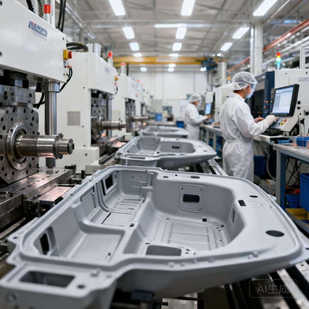
Overview
Warped bezels, flash on latch housings, and cycle-time overruns threaten certification schedules. Panda Molding's Aerospace Interior Component Injection Molding eliminates these defects with scientific molding, ISO9001 quality systems, and a material portfolio that meets FAR 25.853. From prototype to high-volume production, we deliver dimensionally stable, flame-retardant interior parts that fit first time.
", "description": "Aerospace Interior Component Injection Molding — Custom Injection Molding by Panda Molding
\nAerospace interior components—seat-back trays, overhead bin latches, air vent bezels—must combine lightweight design with flame resistance and tight tolerances. Panda Molding's Aerospace Interior Component Injection Molding service tackles the real-world defects that delay programs: warpage, flash, and short shots. Drawing on decades of mold engineering, we pair advanced tooling with real-time process control to hold ±0.05 mm on complex geometries. Our ISO9001-certified facility processes PEEK, PEI (Ultem), and glass-filled polycarbonate, ensuring every plastic part meets FAR 25.853 and your dimensional requirements. As injection molding becomes the go-to for lightweight aircraft interiors[1], we prevent common quality issues[2] through mold flow simulation and strict process discipline.
\n\nService Capabilities
\n- \n
- Tolerances as tight as ±0.05 mm: Achieved through precision tooling and scientific decoupled molding, critical for snap-fit fasteners and light housing lenses. \n
- In-house mold flow simulation & conformal cooling: Optimizes gate, runner, and cooling channel design to minimize warpage and cycle time, referencing best practices for injection mold specifications[3]. \n
- Multi-cavity tooling with hot runner systems: Enables high-volume production of small interior parts like clips and connector housings while maintaining cavity-to-cavity consistency. \n
- Insert molding & overmolding: Integrates metal inserts for threaded bosses, bushings, and EMI shielding directly into the plastic part, reducing assembly steps. \n
- UL94 V-0 material portfolio: Processes PEEK, PEI, PC, PA66 with glass fiber, and PC/ABS blends—all reinforced to meet FAR 25.853 and MIL-STD-810 requirements[4]. \n
Material & Process Selection Guide
\n| Material | \nProcess | \nTypical Interior Applications | \nFailure Boundaries & Mitigation | \n
|---|---|---|---|
| PEEK (Victrex 450G) | \nHigh-temperature injection molding (melt 370–400 °C) | \nSeat components, latch mechanisms, structural brackets | \nWarpage from uneven cooling — mitigated by conformal cooling and post-mold annealing. Complex geometries achieved with precision tooling[5]. | \n
| PEI (Ultem 2300, 30% GF) | \nInjection molding with glass fiber reinforcement | \nLighting housings, air grilles, cabin control panels | \nFlash due to high injection pressure — controlled by valve-gated hot runners and precise clamp force. Design considerations from firstmold[6]. | \n
| Polycarbonate (PC, flame-retardant) | \nStandard injection molding | \nLenses, bezels, indicator covers | \nSink marks in thick sections — eliminated by gas-assist or coring. Material must meet FAR 25.853 (a) for vertical burn[4]. | \n
| Nylon 6/6 (PA66, 30% GF) | \nInjection molding | \nFasteners, clips, cable management brackets | \nDimensional change from moisture absorption — prevented by pre-drying to <0.20% moisture and sealed packaging. Rugged housings for defense electronics[1]. | \n
Industries & Applications
\nOur Aerospace Interior Component Injection Molding serves cabin interiors where flame, smoke, and toxicity requirements are non-negotiable. For seat-back trays and armrests, we mold glass-filled PEI that resists impact and meets FAR 25.853 (a) and (b). Overhead bin latches and door handles benefit from PEEK's strength and wear resistance, while polycarbonate lenses for reading lights demand optical clarity and precise gate placement to avoid flow lines. Air distribution grilles with complex louvers are produced using collapsible cores or gas-assist to maintain uniform wall thickness. From connectors to display bezels, our injection mold solutions mirror the breadth of aerospace plastic injection molding[7], always with full material traceability.
\n\nOur Injection Molding Process
\n- \n
- Material Preparation: High-performance resins like PEEK are dried to <0.02% moisture content in desiccant dryers, preventing hydrolysis and voids in the molded part. \n
- Mold Design & Simulation: We perform Moldflow analysis to predict fill pattern, weld line location, and shrinkage. Conformal cooling channels are designed into the tooling to cut cycle time by up to 20% while minimizing warpage. \n
- Injection Molding: Melt temperature is controlled within a narrow band (e.g., 370–400 °C for PEEK). Injection velocity and packing pressure are profiled to avoid flash and ensure complete cavity fill. Scientific decoupled molding separates fill, pack, and hold phases for dimensional consistency. \n
- Post-Molding Operations: Automated de-gating, annealing for stress relief in high-temp materials, and CNC trimming of critical features. Ultrasonic welding or heat staking is available for multi-component assemblies. \n
Quality Assurance
\nEvery Aerospace Interior Component Injection Molding project undergoes first article inspection (FAI) per AS9102, with CMM dimensional reports, material certifications, and flammability test data. Our ISO9001-certified lab verifies tensile strength (ASTM D638), flexural modulus (ASTM D790), and surface finish to SPI A-2. We maintain lot-level traceability from resin certificate to finished plastic part. RoHS compliance is standard. By integrating quality control directly into the injection mold process—monitoring cavity pressure curves and part weight—we catch defects before they ship. This approach aligns with aerospace injection molding requirements[8] and eliminates the rework that plagues less disciplined suppliers.
\n\nFrequently Asked Questions
\n- \n
- Q: What materials are compatible with Aerospace Interior Component Injection Molding? \n
- A: We process a full range of aerospace-grade thermoplastics: PEEK, PEI (Ultem), polycarbonate, nylon 6/6 with glass fiber, and PC/ABS. All grades meet UL94 V-0 and FAR 25.853. Our engineers can recommend the optimal resin based on your mechanical, thermal, and flammability requirements, including filled and unfilled variants. \n
- Q: What is the typical lead time? \n
- A: Prototype aluminum tooling can deliver T1 samples in 3–4 weeks, enabling rapid design iteration[9]. Production steel tools typically require 6–8 weeks, with first shots ready for qualification. Bridge tooling options are available for low-volume production while production tools are being fabricated. \n
- Q: What are the MOQ requirements? \n
- A: We support low-volume prototyping with as few as 100 parts using aluminum tooling, and high-volume production (10,000+ parts) with multi-cavity steel molds. There is no rigid minimum; we tailor the tooling strategy to your program phase, whether you need flight-test parts or full-rate production. \n
Request a Free Quote
\nUpload your 3D CAD or 2D drawing for a complimentary DFM review and injection molding quote. Our engineers will evaluate draft angles, wall thickness, and gate placement to optimize your part for manufacturability. Expect a detailed proposal within 48 hours, with competitive pricing and no hidden costs. Let's get your interior components flight-ready.
\n\nReferences & Further Reading
\n- \n
- Plastic Injection Molding Trends in Aerospace and Defense | Midwest Mold \n
- Injection Molding Quality Control: Defect Guide | Ronningen Research \n
- Injection Mold Specifications & Plastic Mold Design Guideline | Upmold \n
- Plastic Injection Molding for Aerospace Components: Technical Guide | Machinery Network \n
- Aerospace plastic injection molding | Ensinger \n
- Injection Molding in Aerospace: Key Components, Design Considerations, Materials, and Future Trends | First Mold \n
- Injection Mold Solutions for Aerospace and Aviation | MPP Corp. \n
- Aerospace Components via Injection Molding: Materials and Standards | CoreLMould \n
- Injection Molding for the Aerospace Industry | Fictiv \n